Requirement Process
Informally, a software development process describes an approach to building, deploying, and possibly maintaining software. The Unified Process has emerged as a popular software development process for building object-oriented systems. In particular, the Rational Unified Process or RUP, a detailed refinement of the Unified Process, has been widely adopted.
The Unified Process (UP) combines commonly accepted best practices, such as an iterative lifecycle and risk-driven development, into a cohesive and well-documented description.
The Most Important UP Idea: Iterative Development
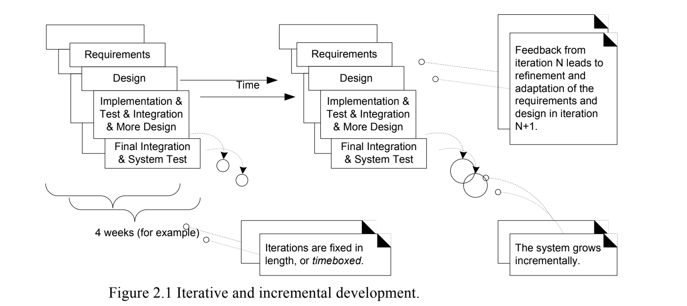
The UP promotes several best practices, but one stands above the others: iterative development. In this approach, development is organized into a series of short, fixed-length (for example, four week) mini-projects called iterations; the outcome of each is a tested, integrated, and executable system. Each iteration includes its own requirements analysis, design, implementation, and testing activities.
The iterative lifecycle is based on the successive enlargement and refinement of a system through multiple iterations, with cyclic feedback and adaptation as core drivers to converge upon a suitable system. The system grows incrementally over time, iteration by iteration, and thus this approach is also known as iterative and incremental development.
Requirement process
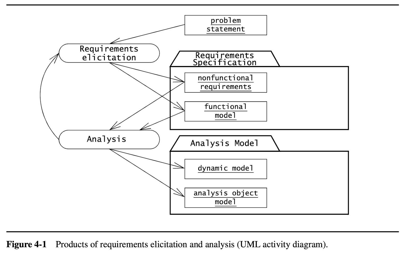
Requirements elicitation focuses on describing the purpose of the system. The client, the developers, and the users identify a problem area and define a system that addresses the problem. Such a definition is called a requirements specification and serves as a contract between the client and the developers. The requirements specification is structured and formalized during analysis to produce an analysis model. Both requirements specification and analysis model represent the same information. They differ only in the language and notation they use; the requirements specification is written in natural language, whereas the analysis model is usually expressed in a formal or semiformal notation. The requirements specification supports the communication with the client and users. The analysis model supports the communication among developers. They are both models of the system in the sense that they attempt to accurately represent the external aspects of the system. Given that both models represent the same aspects of the system, requirements elicitation and analysis occur concurrently and iteratively.
Requirements elicitation and analysis focus only on the user’s view of the system. For example, the system functionality, the interaction between the user and the system, the errors that the system can detect and handle, and the environmental conditions in which the system functions are part of the requirements. The system structure, the implementation technology selected to build the system, the system design, the development methodology, and other aspects not directly visible to the user are not part of the requirements.
Requirements elicitation includes the following activities:
- Identifying actors. During this activity, developers identify the different types of users the future system will support.
- Identifying scenarios. During this activity, developers observe users and develop a set of detailed scenarios for typical functionality provided by the future system. Scenarios are concrete examples of the future system in use. Developers use these scenarios to communicate with the user and deepen their understanding of the application domain.
- Identifying use cases. Once developers and users agree on a set of scenarios, developers derive from the scenarios a set of use cases that completely represent the future system. Whereas scenarios are concrete examples illustrating a single case, use cases are abstractions describing all possible cases. When describing use cases, developers determine the scope of the system.
- Refining use cases. During this activity, developers ensure that the requirements specification is complete by detailing each use case and describing the behavior of the system in the presence of errors and exceptional conditions.
- Identifying relationships among use cases. During this activity, developers identify dependencies among use cases. They also consolidate the use case model by factoring out common functionality. This ensures that the requirements specification is consistent.
- Identifying nonfunctional requirements. During this activity, developers, users, and clients agree on aspects that are visible to the user, but not directly related to functionality. These include constraints on the performance of the system, its documentation, the resources it consumes, its security, and its quality.
During requirements elicitation, developers access many different sources of information, including client-supplied documents about the application domain, manuals and technical documentation of legacy systems that the future system will replace, and most important, the users and clients themselves. Developers interact the most with users and clients during requirements elicitation. We focus on two methods for eliciting information, making decisions with users and clients, and managing dependencies among requirements and other artifacts:
- Joint Application Design (JAD) focuses on building consensus among developers, users, and clients by jointly developing the requirements specification.
- Traceability focuses on recording, structuring, linking, grouping, and maintaining dependencies among requirements and between requirements and other work products.
Requirements Elicitation Concepts
The main requirement elicitation concepts:
- Functional Requirements
- Nonfunctional Requirements
- Completeness, Consistency, Clarity, and Correctness
- Realism, Verifiability, and Traceability
- Greenfield Engineering, Reengineering, and Interface Engineering
Functional Requirement
Functional requirements describe the interactions between the system and its environment independent of its implementation. The environment includes the user and any other external system with which the system interacts. For example, Figure 4-2 is an example of functional requirements for SatWatch, a watch that resets itself without user intervention:
|
SatWatch is a wrist watch that displays the time based on its current location. SatWatch uses GPS satellites (Global Positioning System) to determine its location and internal data structures to convert this location into a time zone. The information stored in SatWatch and its accuracy measuring time is such that the watch owner never needs to reset the time. SatWatch adjusts the time and date displayed as the watch owner crosses time zones and political boundaries. For this reason, SatWatch has no buttons or controls available to the user. SatWatch determines its location using GPS satellites and, as such, suffers from the same limitations as all other GPS devices (e.g., inability to determine location at certain times of the day in mountainous regions). During blackout periods, SatWatch assumes that it does not cross a time zone or a political boundary. SatWatch corrects its time zone as soon as a blackout period ends. SatWatch has a two-line display showing, on the top line, the time (hour, minute, second, time zone) and on the bottom line, the date (day, date, month, year). The display technology used is such that the watch owner can see the time and date even under poor light conditions. When political boundaries change, the watch owner may upgrade the software of the watch using the WebifyWatch device (provided with the watch) and a personal computer connected to the Internet. |
Figure 4-2 Functional requirements for SatWatch.
The above functional requirements focus only on the possible interactions between SatWatch and its external world (i.e., the watch owner, GPS, and WebifyWatch). The above description does not focus on any of the implementation details (e.g., processor, language, display technology).
Non-functional Requirements:
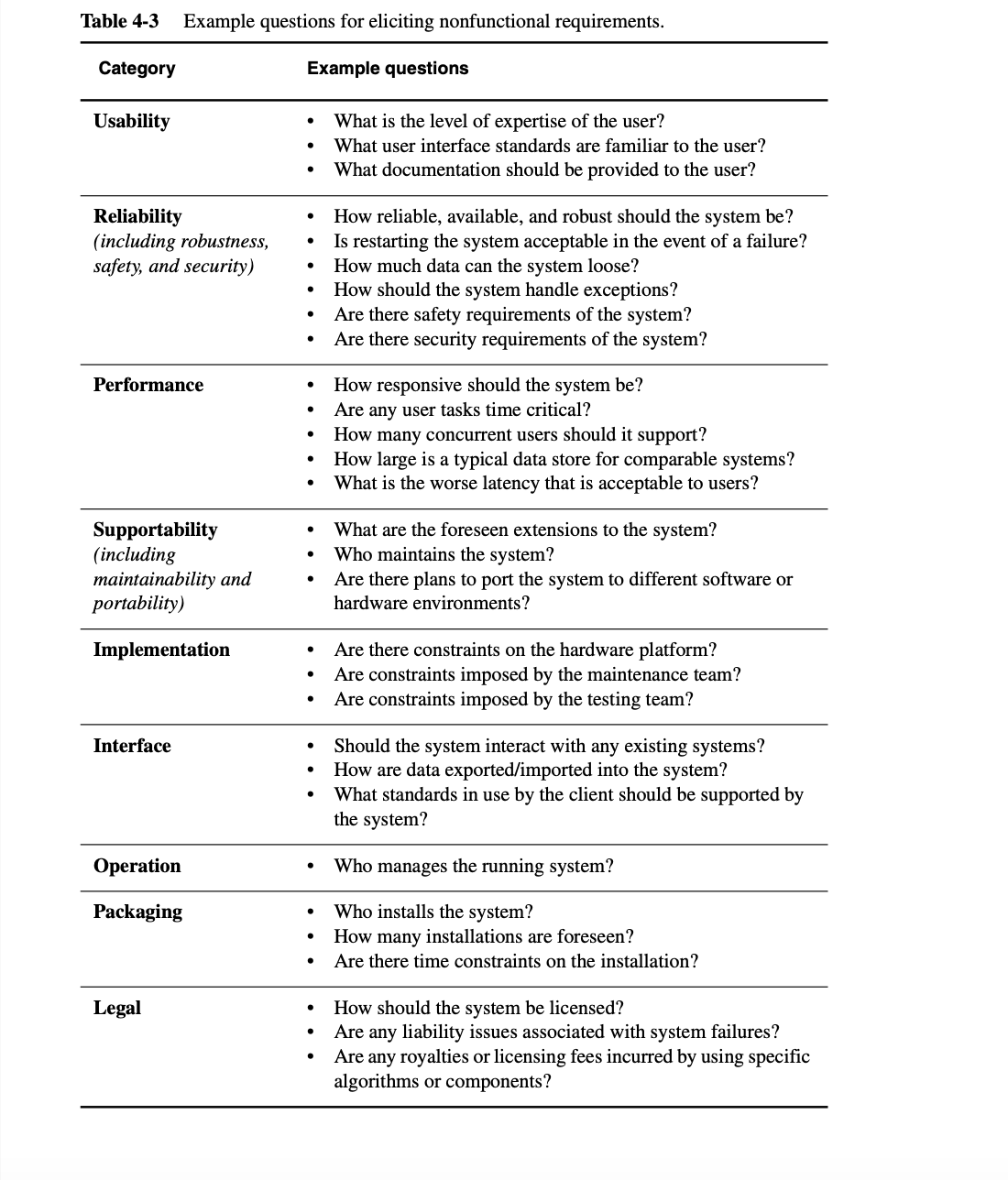
Nonfunctional requirements describe aspects of the system that are not directly related to the functional behavior of the system. Nonfunctional requirements include a broad variety of requirements that apply to many different aspects of the system, from usability to performance. The FURPS+ model2 used by the Unified Process [Jacobson et al., 1999] provides the following categories of nonfunctional requirements:
- Usability is the ease with which a user can learn to operate, prepare inputs for, and interpret outputs of a system or component. Usability requirements include, for example, conventions adopted by the user interface, the scope of online help, and the level of user documentation. Often, clients address usability issues by requiring the developer to follow user interface guidelines on color schemes, logos, and fonts.
- Reliability is the ability of a system or component to perform its required functions under stated conditions for a specified period of time. Reliability requirements include, for example, an acceptable mean time to failure and the ability to detect specified faults or to withstand specified security attacks. More recently, this category is often replaced by dependability, which is the property of a computer system such that reliance can justifiably be placed on the service it delivers. Dependability includes reliability, robustness (the degree to which a system or component can function correctly in the presence of invalid inputs or stressful environment conditions), and safety (a measure of the absence of catastrophic consequences to the environment).
- Performance requirements are concerned with quantifiable attributes of the system, such as response time (how quickly the system reacts to a user input), throughput (how much work the system can accomplish within a specified amount of time), availability (the degree to which a system or component is operational and accessible when required for use), and accuracy.
- Supportability requirements are concerned with the ease of changes to the system after deployment, including for example, adaptability (the ability to change the system to deal with additional application domain concepts), maintainability (the ability to change the system to deal with new technology or to fix defects), and internationalization (the ability to change the system to deal with additional international conventions, such as languages, units, and number formats). The ISO 9126 standard on software quality [ISO Std. 9126], similar to the FURPS+ model, replaces this category with two categories: maintainability and portability (the ease with which a system or component can be transferred from one hardware or software environment to another).
|
FURPS+ is an acronym using the first letter of the requirements categories: Functionality, Usability, Reliability, Performance, and Supportability. The + indicates the additional subcategories. The FURPS model was originally proposed by [Grady, 1992].
|
The FURPS+ model provides additional categories of requirements typically also included under the general label of nonfunctional requirements:
- Implementation requirements are constraints on the implementation of the system, including the use of specific tools, programming languages, or hardware platforms.
- Interface requirements are constraints imposed by external systems, including legacy systems and interchange formats.
- Operations requirements are constraints on the administration and management of the system in the operational setting.
- Packaging requirements are constraints on the actual delivery of the system (e.g., constraints on the installation media for setting up the software).
- Legal requirements are concerned with licensing, regulation, and certification issues. An example of a legal requirement is that software developed for the U.S. federal government must comply with Section 508 of the Rehabilitation Act of 1973, requiring that government information systems must be accessible to people with disabilities.
Nonfunctional requirements that fall into the URPS categories are called quality requirements of the system. Nonfunctional requirements that fall into the implementation, interface, operations, packaging, and legal categories are called constraints or pseudo requirements.
|
[Supportability requirement]
|
Fig. Non-functional requirement
Completeness, Consistency, Clarity, and Correctness
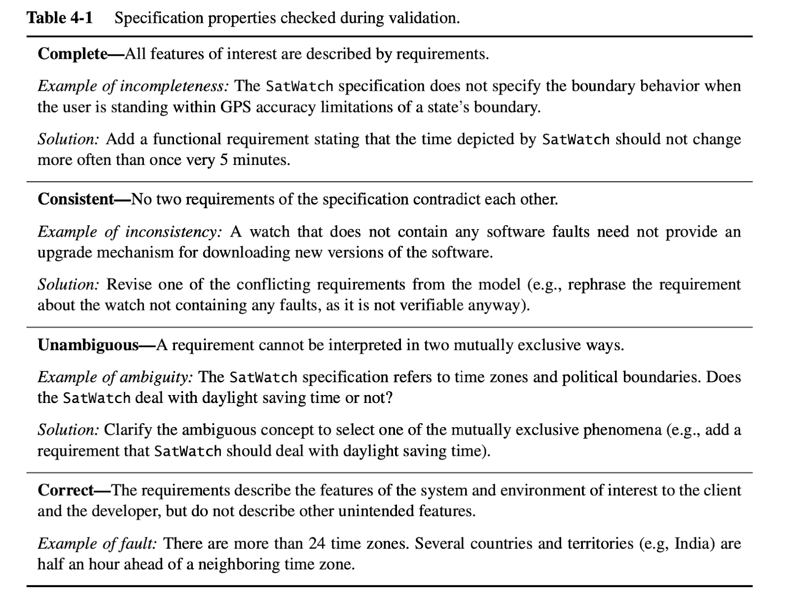
Requirements are continuously validated with the client and the user. Validation is a critical step in the development process, given that both the client and the developer depend on the requirements specification. Requirement validation involves checking that the specification is complete, consistent, unambiguous, and correct. It is complete if all possible scenarios through the system are described, including exceptional behavior (i.e., all aspects of the system are represented in the requirements model). The requirements specification is consistent if it does not contradict itself. The requirements specification is unambiguous if exactly one system is defined (i.e., it is not possible to interpret the specification two or more different ways). A specification is correct if it accurately represents the system that the client needs and that the developers intend to build (i.e., everything in the requirements model accurately represents an aspect of the system to the satisfaction of both client and developer).
The correctness and completeness of a requirements specification are often difficult to establish, especially before the system exists. Given that the requirements specification serves as a contractual basis between the client and the developers, the requirements specification must be carefully reviewed by both parties. Additionally, parts of the system that present a high risk should be prototyped or simulated to demonstrate their feasibility or to obtain feedback from the user. In the case of SatWatch described above, a mock-up of the watch would be built using a traditional watch and users surveyed to gather their initial impressions. A user may remark that she wants the watch to be able to display both American and European date formats.
Realism, Verifiability, and Traceability
Three more desirable properties of a requirements specification are that it be realistic, verifiable, and traceable. The requirements specification is realistic if the system can be implemented within constraints. The requirements specification is verifiable if, once the system is built, repeatable tests can be designed to demonstrate that the system fulfills the requirements specification. For example, a mean time to failure of a hundred years for SatWatch would be difficult to verify (assuming it is realistic in the first place). The following requirements are additional examples of nonverifiable requirements:
- The product shall have a good user interface.—Good is not defined.
- The product shall be error free.—Requires large amounts of resources to establish.
- The product shall respond to the user within 1 second for most cases.—“Most cases” is not defined.
A requirements specification is traceable if each requirement can be traced throughout the software development to its corresponding system functions, and if each system function can be traced back to its corresponding set of requirements. Traceability includes also the ability to track the dependencies among requirements, system functions, and the intermediate design artifacts, including system components, classes, methods, and object attributes. Traceability is critical for developing tests and for evaluating changes. When developing tests, traceability enables a tester to assess the coverage of a test case, that is, to identify which requirements are tested and which are not. When evaluating changes, traceability enables the analyst and the developers to identify all components and system functions that the change would impact.
Greenfield Engineering, Reengineering, and Interface Engineering
Requirements elicitation activities can be classified into three categories, depending on the source of the requirements. In greenfield engineering, the development starts from scratch—no prior system exists—so the requirements are extracted from the users and the client. A greenfield engineering project is triggered by a user need or the creation of a new market. SatWatch is a greenfield engineering project.
A reengineering project is the redesign and reimplementation of an existing system triggered by technology enablers or by business processes [Hammer & Champy, 1993]. Sometimes, the functionality of the new system is extended, but the essential purpose of the system remains the same. The requirements of the new system are extracted from an existing system.
An interface engineering project is the redesign of the user interface of an existing system. The legacy system is left untouched except for its interface, which is redesigned and reimplemented. This type of project is a reengineering project in which the legacy system cannot be discarded without entailing high costs.
Requirements Elicitation Activities
Requirements elicitation activities include
- Identifying Actors
- Identifying Scenarios
- Identifying Use Cases
- Refining Use Cases
- Identifying Relationships Among Actors and Use Cases
- Identifying Initial Analysis Objects
- Identifying Nonfunctional Requirements
Identifying Actors
Actors represent external entities that interact with the system. An actor can be human or an external system.
Consider a more complex example, FRIEND, a distributed information system for accident management [Bruegge et al., 1994]. It includes many actors, such as FieldOfficer, who represents the police and fire officers who are responding to an incident, and Dispatcher, the police officer responsible for answering 911 calls and dispatching resources to an incident. FRIEND supports both actors by keeping track of incidents, resources, and task plans. It also has access to multiple databases, such as a hazardous materials database and emergency operations procedures. The FieldOfficer and the Dispatcher actors interact through different interfaces: FieldOfficers access FRIEND through a mobile personal assistant, Dispatchers access FRIEND through a workstation (see Figure 4-5).
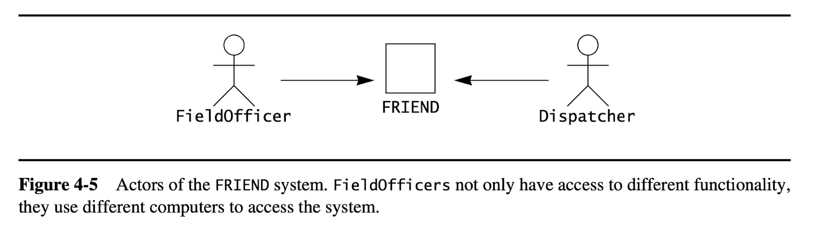
Actors are role abstractions and do not necessarily directly map to persons. The same person can fill the role of FieldOfficer or Dispatcher at different times. However, the functionality they access is substantially different. For that reason, these two roles are modeled as two different actors.
The first step of requirements elicitation is the identification of actors. This serves both to define the boundaries of the system and to find all the perspectives from which the developers need to consider the system. When the system is deployed into an existing organization (such as a company), most actors usually exist before the system is developed: they correspond to roles in the organization.
During the initial stages of actor identification, it is hard to distinguish actors from objects. For example, a database subsystem can at times be an actor, while in other cases it can be part of the system. Note that once the system boundary is defined, there is no trouble distinguishing between actors and such system components as objects or subsystems. Actors are outside of the system boundary; they are external. Subsystems and objects are inside the system boundary; they are internal. Thus, any external software system using the system to be developed is an actor. When identifying actors, developers can ask the following questions:
|
Questions for identifying actors • Which user groups are supported by the system to perform their work? • Which user groups execute the system’s main functions? • Which user groups perform secondary functions, such as maintenance and administration? • With what external hardware or software system will the system interact? |
In the FRIEND example, these questions lead to a long list of potential actors: fire fighter, police officer, dispatcher, investigator, mayor, governor, an EPA hazardous material database, system administrator, and so on. We then need to consolidate this list into a small number of actors, who are different from the point of view of the usage of the system. For example, a fire fighter and a police officer may share the same interface to the system, as they are both involved with a single incident in the field. A dispatcher, on the other hand, manages multiple concurrent incidents and requires access to a larger amount of information. The mayor and the governor will not likely interact directly with the system, but will use the services of a trained operator instead.
Once the actors are identified, the next step in the requirements elicitation activity is to determine the functionality that will be accessible to each actor. This information can be extracted using scenarios and formalized using use cases.
Identifying Scenarios
A scenario is “a narrative description of what people do and experience as they try to make use of computer systems and applications” [Carroll, 1995]. A scenario is a concrete, focused, informal description of a single feature of the system from the viewpoint of a single actor. Scenarios cannot (and are not intended to) replace use cases, as they focus on specific instances and concrete events (as opposed to complete and general descriptions). However, scenarios enhance requirements elicitation by providing a tool that is understandable to users and clients.
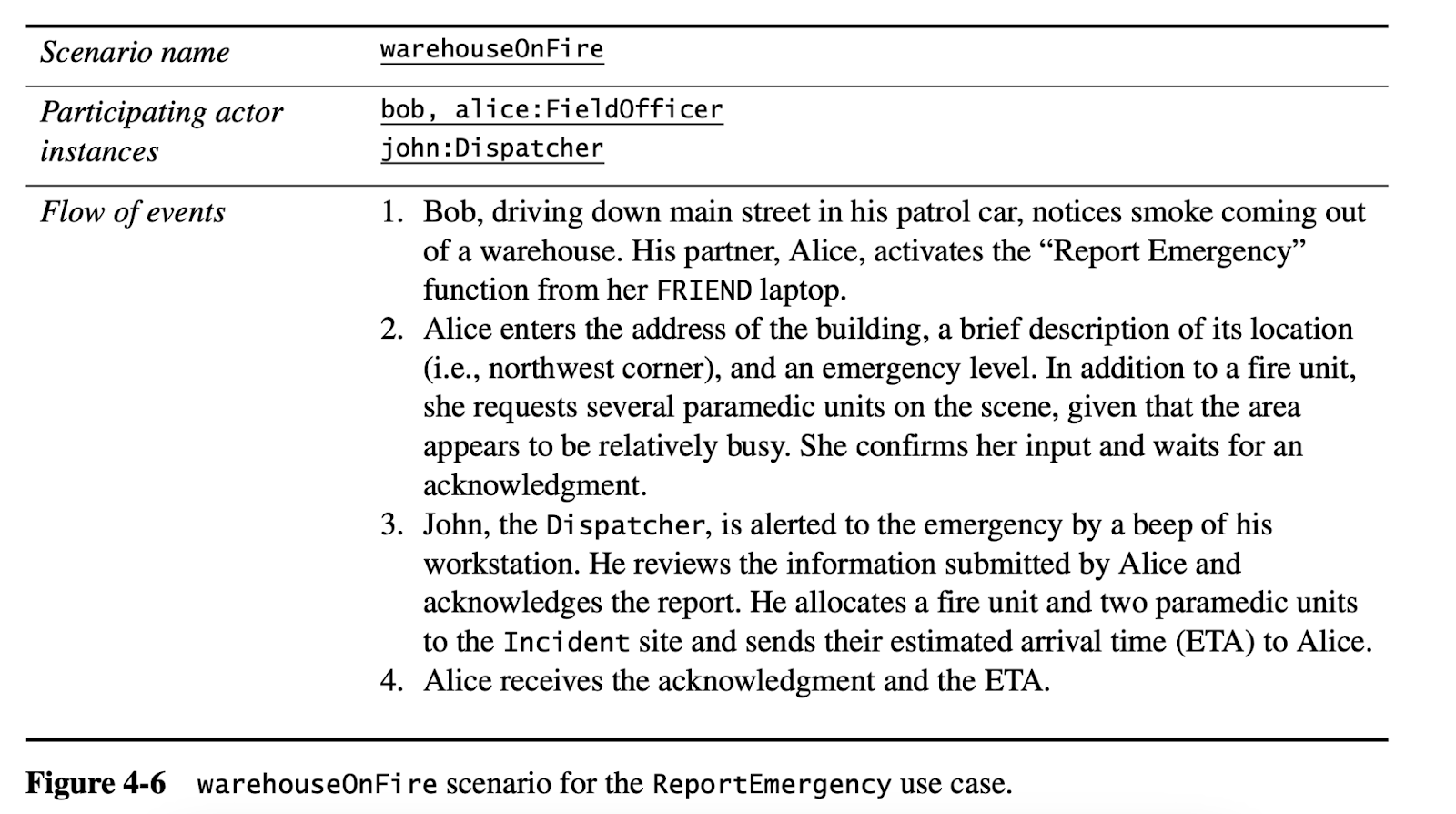
Figure 4-6 is an example of scenario for the FRIEND system, an information system for incident response. In this scenario, a police officer reports a fire and a Dispatcher initiates the incident response. Note that this scenario is concrete, in the sense that it describes a single instance. It does not attempt to describe all possible situations in which a fire incident is reported.
In the FRIEND example, we identify four scenarios that span the type of tasks the system is expected to support:
• warehouseOnFire (Figure 4-6): A fire is detected in a warehouse; two field officers arrive at the scene and request resources.
• fenderBender: A car accident without casualties occurs on the highway. Police officers document the incident and manage traffic while the damaged vehicles are towed away.
• catInATree: A cat is stuck in a tree. A fire truck is called to retrieve the cat. Because the incident is low priority, the fire truck takes time to arrive at the scene. In the meantime, the impatient cat owner climbs the tree, falls, and breaks a leg, requiring an ambulance to be dispatched.
• earthQuake: An unprecedented earthquake seriously damages buildings and roads, spanning multiple incidents and triggering the activation of a statewide emergency operations plan. The governor is notified. Road damage hampers incident response.
The emphasis for developers during actor identification and scenario identification is to understand the application domain. This results in a shared understanding of the scope of the system and of the user work processes to be supported. Once developers have identified and described actors and scenarios, they formalize scenarios into use cases.
Identifying Use Cases
A scenario is an instance of a use case; that is, a use case specifies all possible scenarios for a given piece of functionality. A use case is initiated by an actor. After its initiation, a use case may interact with other actors, as well. A use case represents a complete flow of events through the system in the sense that it describes a series of related interactions that result from its initiation.
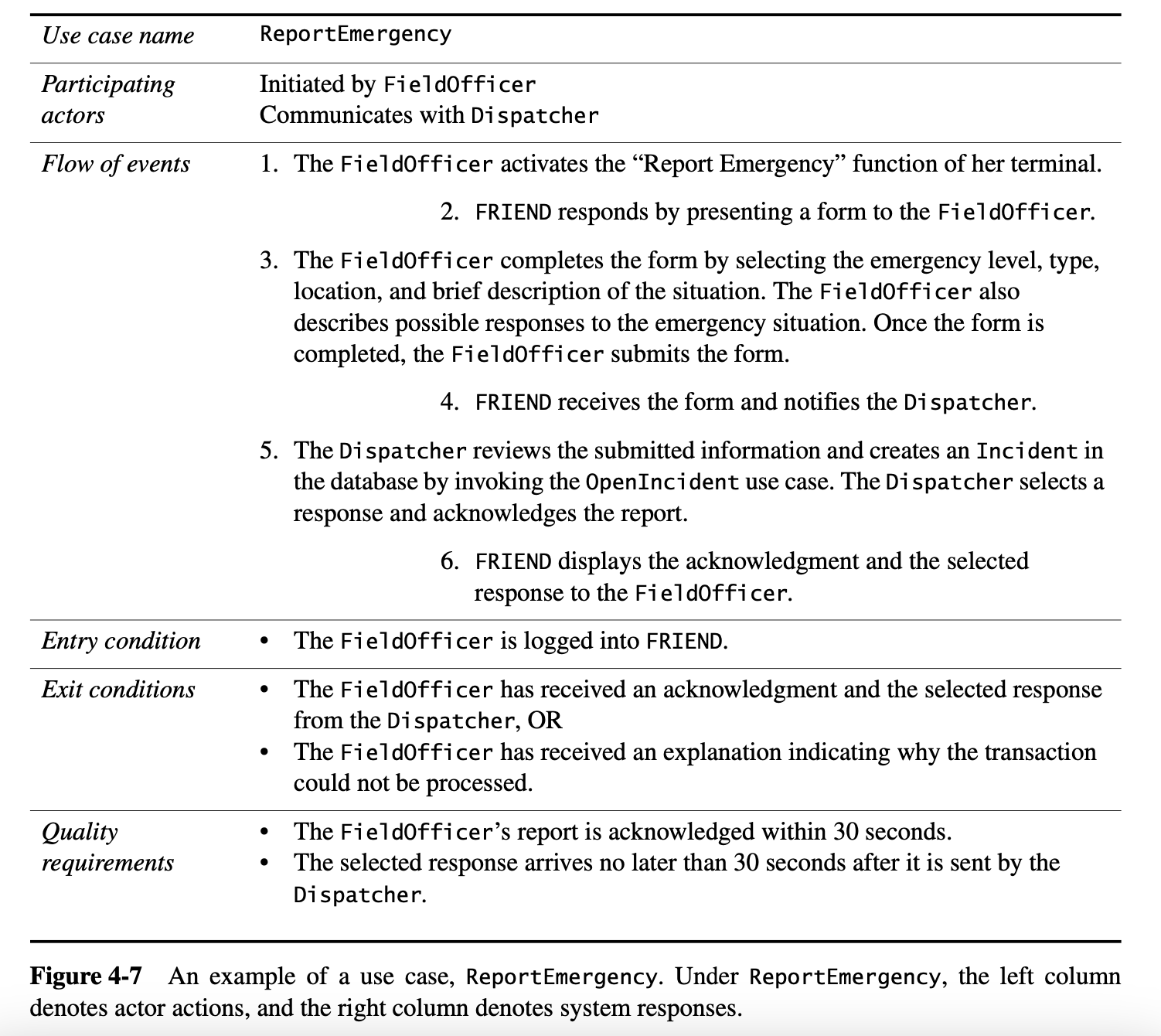
Figure 4-7 depicts the use case ReportEmergency of which the scenario warehouseOnFire (see Figure 4-6) is an instance. The FieldOfficer actor initiates this use case by activating the “Report Emergency” function of FRIEND. The use case completes when the FieldOfficer actor receives an acknowledgment that an incident has been created. The steps in the flow of events are indented to denote who initiates the step. Steps 1 and 3 are initiated by the actor, while steps 2 and 4 are initiated by the system. This use case is general and encompasses a range of scenarios. For example, the ReportEmergency use case could also apply to the fenderBender scenario. Use cases can be written at varying levels of detail as in the case of scenarios.
|
Simple Use Case Writing Guide • Use cases should be named with verb phrases. The name of the use case should indicate what the user is trying to accomplish (e.g., ReportEmergency, OpenIncident). • Actors should be named with noun phrases (e.g., FieldOfficer, Dispatcher, Victim). • The boundary of the system should be clear. Steps accomplished by the actor and steps accomplished by the system should be distinguished (e.g., in Figure 4-7, system actions are indented to the right). • Use case steps in the flow of events should be phrased in the active voice. This makes it explicit who accomplished the step. • The causal relationship between successive steps should be clear. • A use case should describe a complete user transaction (e.g., the ReportEmergency use case describes all the steps between initiating the emergency reporting and receiving an acknowledgment). • Exceptions should be described separately. • A use case should not describe the user interface of the system. This takes away the focus from the actual steps accomplished by the user and is better addressed with visual mock-ups (e.g., the ReportEmergency only refers to the “Report Emergency” function, not the menu, the button, nor the actual command that corresponds to this function). • A use case should not exceed two or three pages in length. Otherwise, use include and extend relationships to decompose it in smaller use cases, as explained in Section 4.4.5. |
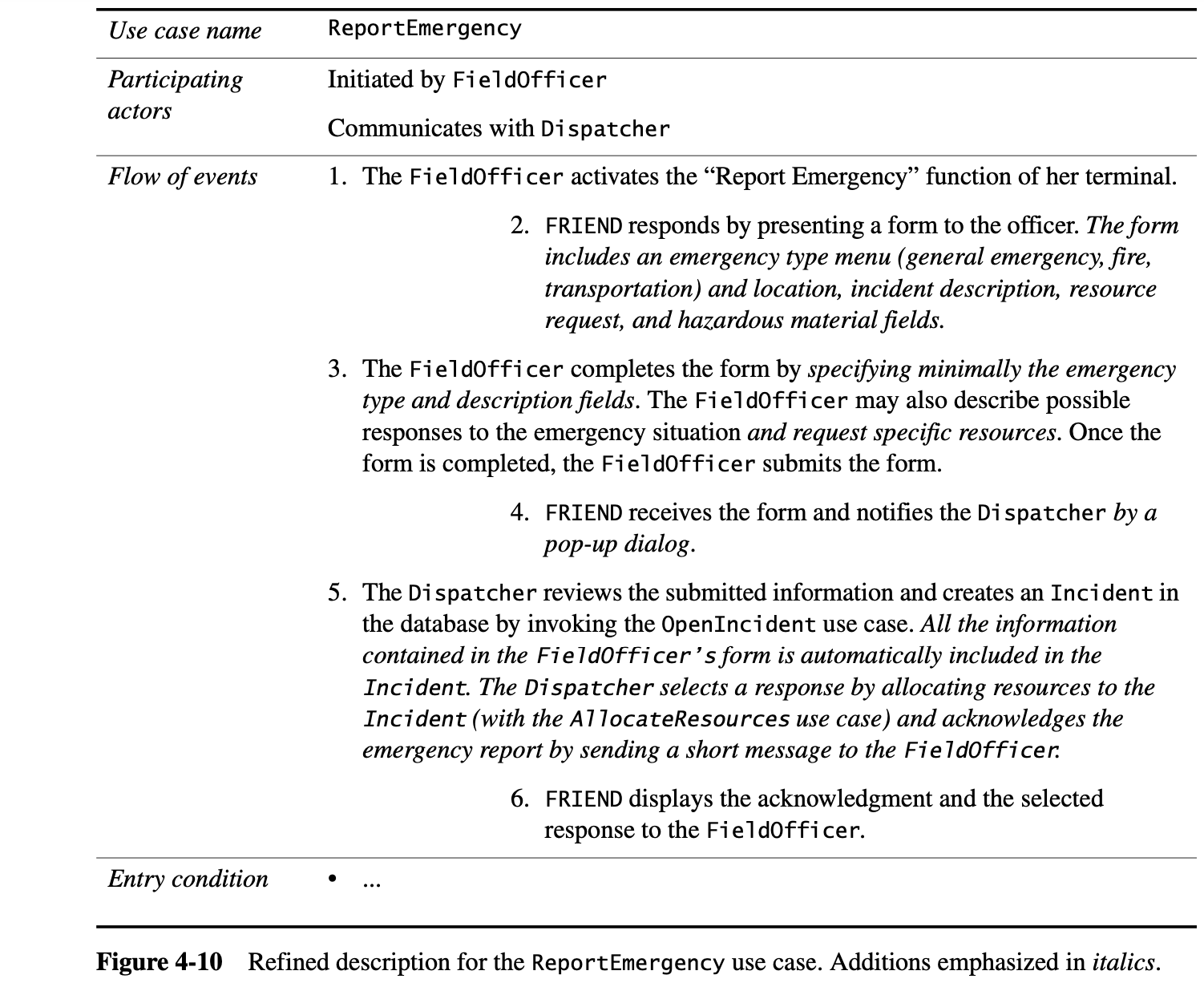
Refining Use Cases
Figure 4-10 is a refined version of the ReportEmergency use case. It has been extended to include details about the type of incidents known to FRIEND and detailed interactions indicating how the Dispatcher acknowledges the FieldOfficer.
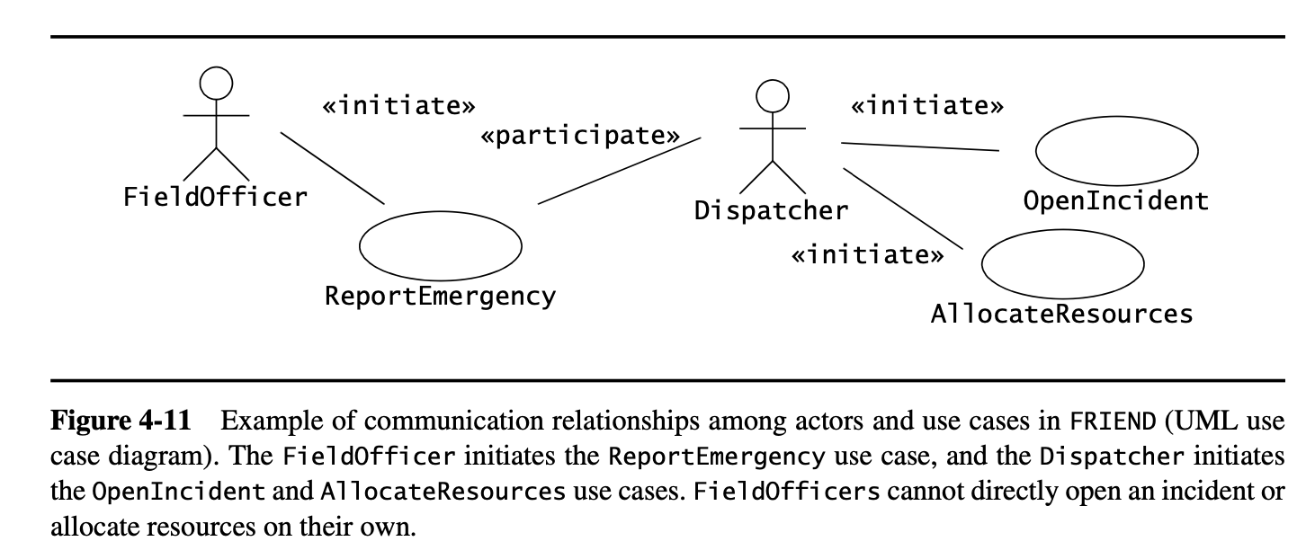
Identifying Relationships among Actors and Use Cases
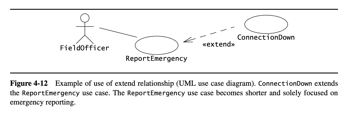
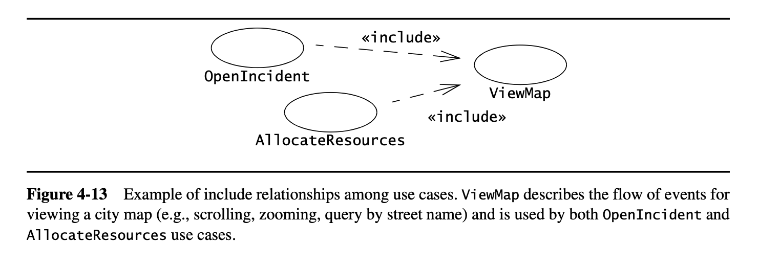
Even medium-sized systems have many use cases. Relationships among actors and use cases enable the developers and users to reduce the complexity of the model and increase its understandability. We use communication relationships between actors and use cases to describe the system in layers of functionality. We use extend relationships to separate exceptional and common flows of events. We use include relationships to reduce redundancy among use cases.
Identifying Initial Analysis Objects
One of the first obstacles developers and users encounter when they start collaborating with each other is differing terminology. Although developers eventually learn the users’ terminology, this problem is likely to be encountered again when new developers are added to the project. Misunderstandings result from the same terms being used in different contexts and with different meanings.
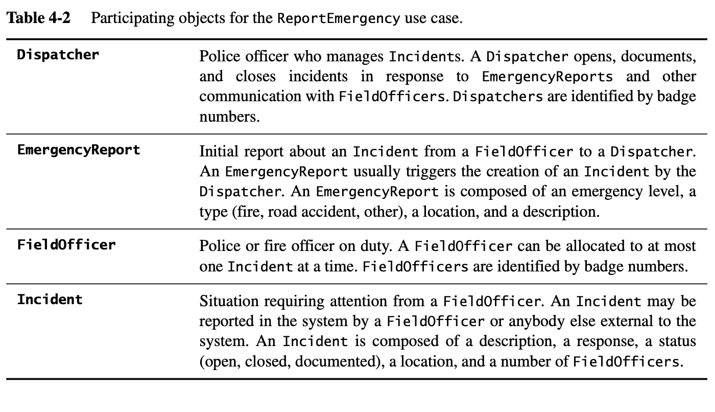
To establish a clear terminology, developers identify the participating objects for each use case. Developers should identify, name, and describe them unambiguously and collate them into a glossary.3 Building this glossary constitutes the first step toward analysis, which we discuss in the next chapter.
The glossary is included in the requirements specification and, later, in the user manuals. Developers keep the glossary up to date as the requirements specification evolves. The benefits of the glossary are manyfold: new developers are exposed to a consistent set of definitions, a single term is used for each concept (instead of a developer term and a user term), and each term has a precise and clear official meaning.
The identification of participating objects results in the initial analysis object model. The identification of participating objects during requirements elicitation only constitutes a first step toward the complete analysis object model. The complete analysis model is usually not used as a means of communication between users and developers, as users are often unfamiliar with object-oriented concept.
Identifying Nonfunctional Requirements
Nonfunctional requirements describe aspects of the system that are not directly related to its functional behavior. Nonfunctional requirements span a number of issues, from user interface look and feel to response time requirements to security issues. Nonfunctional requirements are defined at the same time as functional requirements because they have as much impact on the development and cost of the system.