An Example:
Before diving into the details of requirements analysis and OOA/D, this section presents a birds-eye view of a few key steps and diagrams, using a simple example—a "dice game" in which a player rolls two die. If the total is seven, they win; otherwise, they lose.
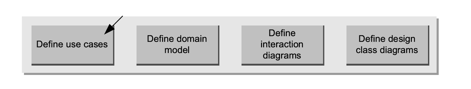
Define Use Cases
Requirements analysis may include a description of related domain processes; these can be written as use cases. Use cases are not an object-oriented artifact—they are simply written stories. For example, here is a brief version of the
Play a Dice Game use case:
- Play a Dice Game: A player picks up and rolls the dice. If the dice face value total seven, they win; otherwise, they lose.
Define a Domain Model
Object-oriented analysis is concerned with creating a description of the domain from the perspective of classification by objects. A decomposition of the domain involves an identification of the concepts, attributes, and associations that are considered noteworthy. The result can be expressed in a domain model, which is illustrated in a set of diagrams that show domain concepts or objects.
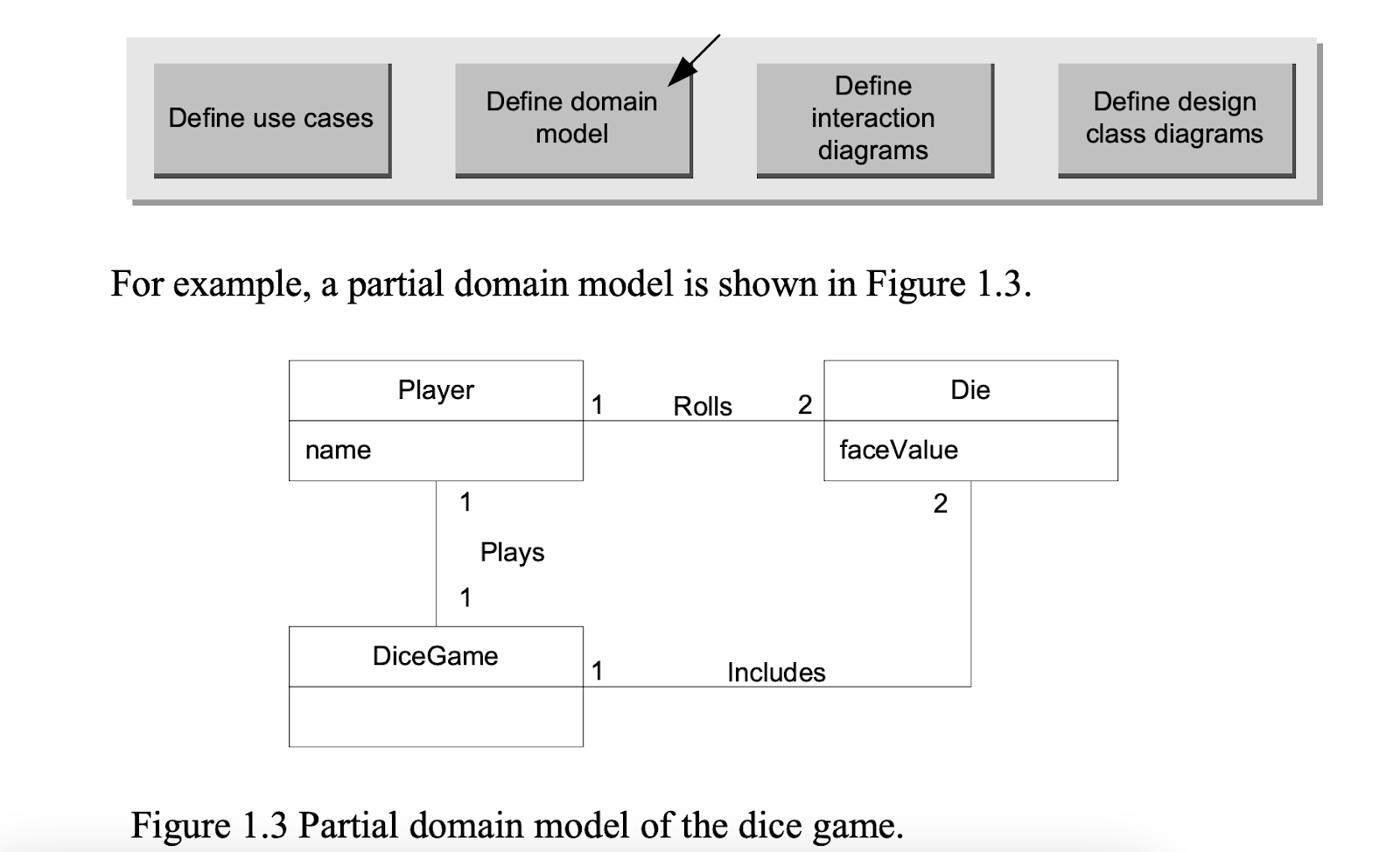
This model illustrates the noteworthy concepts Player, Die, and DiceGame, with their associations and attributes. Note that a domain model is not a description of software objects; it is a visualization of concepts in the real-world domain.
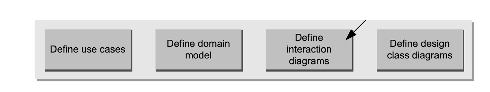
Define Interaction Diagrams
Object-oriented design is concerned with defining software objects and their collaborations. A common notation to illustrate these collaborations is the interaction diagram. It shows the flow of messages between software objects, and thus the invocation of methods.
For example, assume that a software implementation of the dice game is desired. The interaction diagram in Figure 1.4 illustrates the essential step of playing, by sending messages to instances of the DiceGame and Die classes.
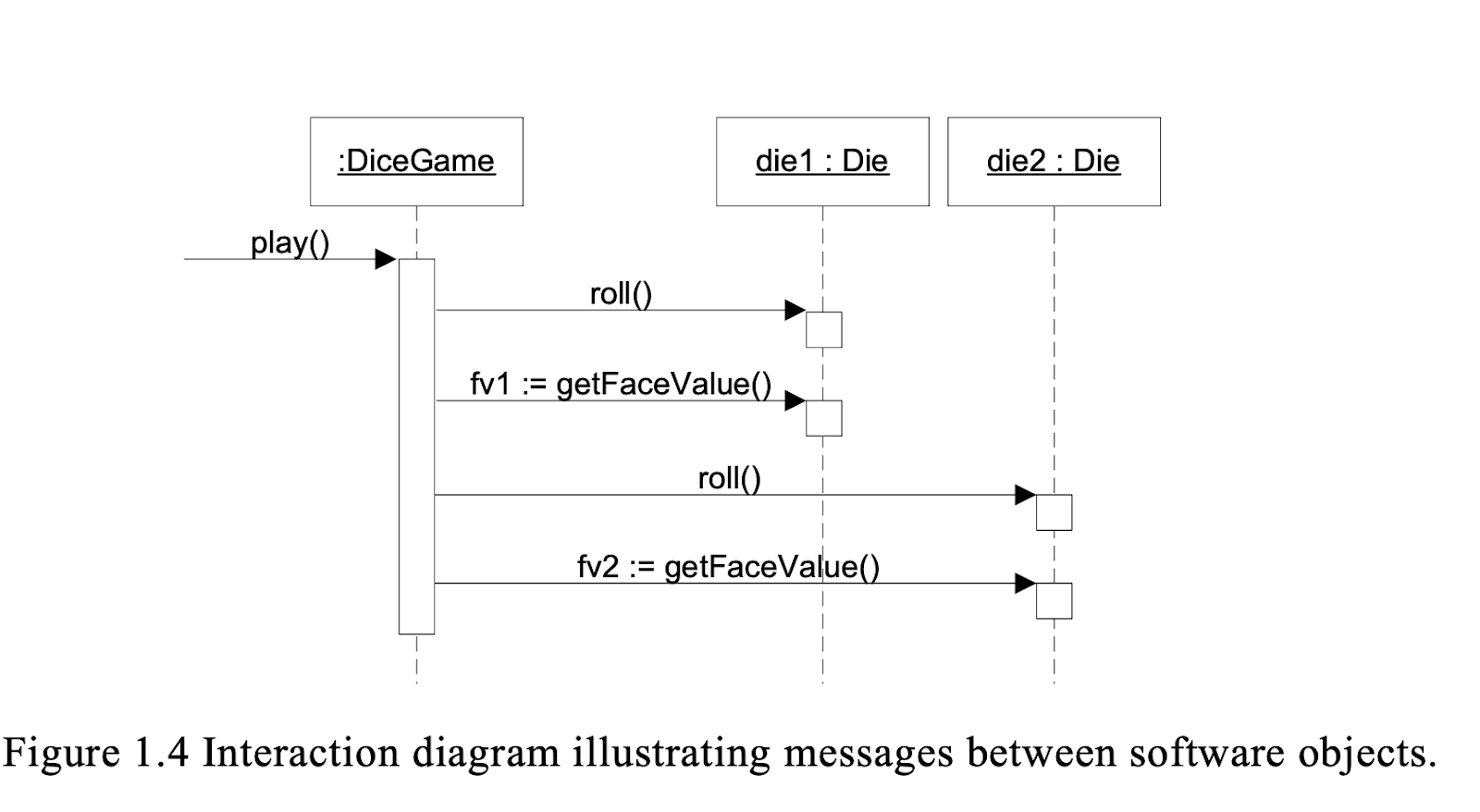
Notice that although in the real world a player rolls the dice, in the software design the DiceGame object "rolls" the dice (that is, sends messages to Die objects). Software object designs and programs do take some inspiration from real-world domains, but they are not direct models or simulations of the real world.
Define Design Class Diagrams
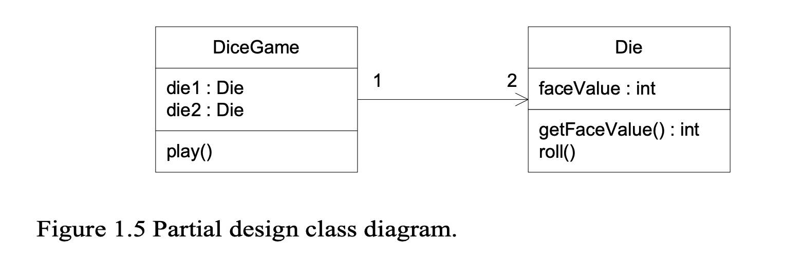
In addition to a dynamic view of collaborating objects shown in interaction diagrams, it is useful to create a static view of the class definitions with a design class diagram. This illustrates the attributes and methods of the classes.
For example, in the dice game, an inspection of the interaction diagram leads to the partial design class diagram shown in Figure 1.5. Since a play message is sent to a DiceGame object, the DiceGame class requires a play method, while class Die requires a roll and getFaceValue method. In contrast to the domain model, this diagram does not illustrate real-world concepts; rather, it shows software classes.
What is UML?
The Unified Modeling Language (UML) is a language for specifying, visualizing, constructing, and documenting the artifacts of software systems, as well as for business modeling and other non-software systems