Representation and Application
A graph in data structures is a non-linear data structure consisting of a collection of nodes (vertices) connected by edges. Graphs are used to represent relationships between pairs of objects. They are widely used in computer science and various applications due to their flexibility and ability to model complex relationships.
The key components of a graph:
Vertices (Nodes): These are the fundamental units of a graph. Each vertex represents an entity or object, and it can store additional information if needed.
Edges: Edges are the connections between pairs of vertices. They represent relationships or connections between the entities represented by the vertices. Edges can be directed or undirected, indicating the directionality of the relationship.
Weight: Edges in a graph can have a weight or cost associated with them. This weight can represent various metrics such as distance, time, cost, etc. Weighted graphs are used when the relationships between vertices have associated costs.
Applications of Graph
Networks: Graphs are used to model different types of networks such as social networks, computer networks, transportation networks, etc. In a social network, vertices represent individuals, and edges represent relationships (friendships) between them.
Routing and Pathfinding: Graphs are extensively used in routing algorithms, where vertices represent locations, and edges represent connections between them. Algorithms like Dijkstra's algorithm and A* search algorithm use graphs to find the shortest path between two nodes in a network.
Data Representation: Graphs are used to represent data structures like trees, linked lists, and various other complex structures. For instance, a binary tree can be represented as a graph where each node has at most two children.
Recommendation Systems: In recommendation systems, graphs can be used to represent user-item interactions. Vertices represent users and items, and edges represent interactions or relationships between them. Algorithms can then analyze this graph to generate personalized recommendations.
Circuit Design: Graphs are used to model electronic circuits, with vertices representing components and edges representing connections between them. Graph algorithms help in analyzing and optimizing circuit designs.
Definition
A graph G is defined as an ordered set (V, E), where V(G) represents the set of vertices and E(G) represents the edges that connect these vertices.
Above figure shows a graph with V(G) = {A, B, C, D and E} and E(G) = {(A, B), (B, C), (A, D), (B, D), (D, E), (C, E)}. Note that there are five vertices or nodes and six edges in the graph.
A graph can be directed or undirected. In an undirected graph, edges do not have any direction associated with them. That is, if an edge is drawn between nodes A and B, then the nodes can be traversed from A to B as well as from B to A. Figure above shows an undirected graph because it does not give any information about the direction of the edges.
Look at Fig. above which shows a directed graph. In a directed graph, edges form an ordered pair. If there is an edge from A to B, then there is a path from A to B but not from B to A. The edge (A, B) is said to initiate from node A (also known as initial node) and terminate at node B (terminal node).
Graph Terminology
Path
A path can be defined as the sequence of nodes that are followed in order to reach some terminal node V from the initial node U.
Closed Path
A path will be called a closed path if the initial node is the same as the terminal node. A path will be a closed path if V0=VN.
Simple Path
If all the nodes of the graph are distinct with an exception V0=VN, then such path P is called a closed simple path.
Cycle
A cycle can be defined as the path which has no repeated edges or vertices except the first and last vertices.
Connected Graph
A connected graph is the one in which some path exists between every two vertices (u, v) in V. There are no isolated nodes in the connected graph.
Complete Graph
A complete graph is the one in which every node is connected with all other nodes. A complete graph contains n(n-1)/2 edges where n is the number of nodes in the graph.
Weighted Graph
In a weighted graph, each edge is assigned with some data such as length or weight. The weight of an edge e can be given as w(e) which must be a positive (+) value indicating the cost of traversing the edge.
Digraph
A digraph is a directed graph in which each edge of the graph is associated with some direction and the traversing can be done only in the specified direction.
Loop
An edge that is associated with the similar endpoints can be called a Loop. Adjacent Nodes
If two nodes u and v are connected via an edge e, then the nodes u and v are called neighbors or adjacent nodes.
Degree of the Node
A degree of a node is the number of edges that are connected with that node. A node with degree 0 is called an isolated node.
Graph Representation
By Graph representation, we simply mean the technique which is to be used in order to store some graph into the computer's memory.
There are two ways to store Graph into the computer's memory.
1. Sequential Representation
In sequential representation, we use an adjacency matrix to store the mapping represented by vertices and edges. In the adjacency matrix, the rows and columns are represented by the graph vertices. A graph having n vertices, will have a dimension n x n.
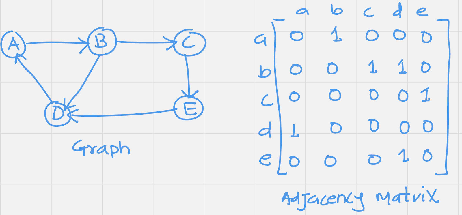
An entry Mij in the adjacency matrix representation of an undirected graph G will be 1 if there exists an edge between Vi and Vj. An undirected graph and its adjacency matrix representation is shown in the following figure:
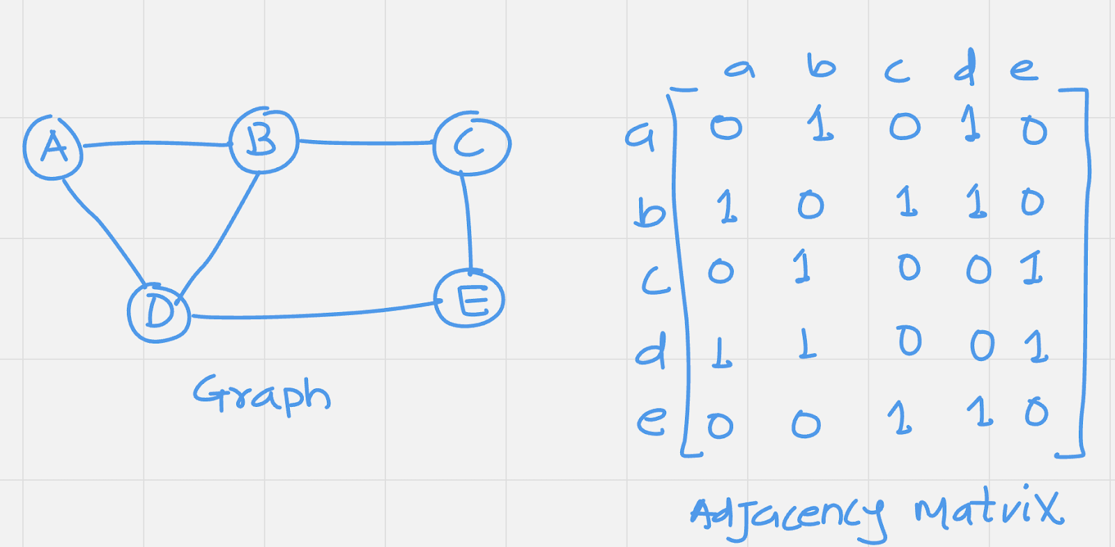
In the above figure, we can see the mapping among the vertices (A, B, C, D, E) is represented by using the adjacency matrix which is also shown in the figure.
There exists different adjacency matrices for the directed and undirected graph. In directed graph, an entry Aij will be 1 only when there is an edge directed from Vi to Vj.
A directed graph and its adjacency matrix representation is shown in the following figure.
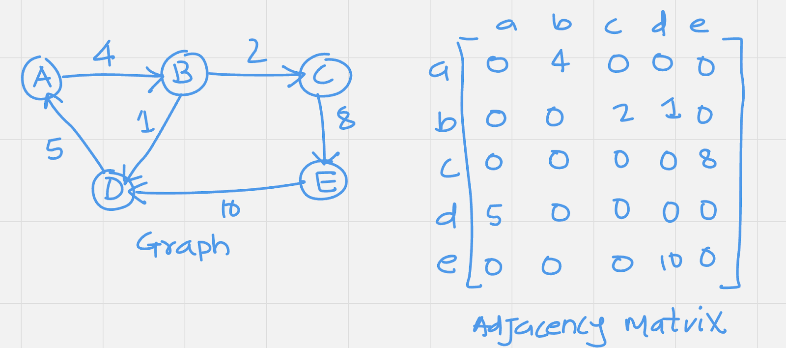
Representation of weighted directed graph is different. Instead of filling the entry by 1, the Non- zero entries of the adjacency matrix are represented by the weight of respective edges.
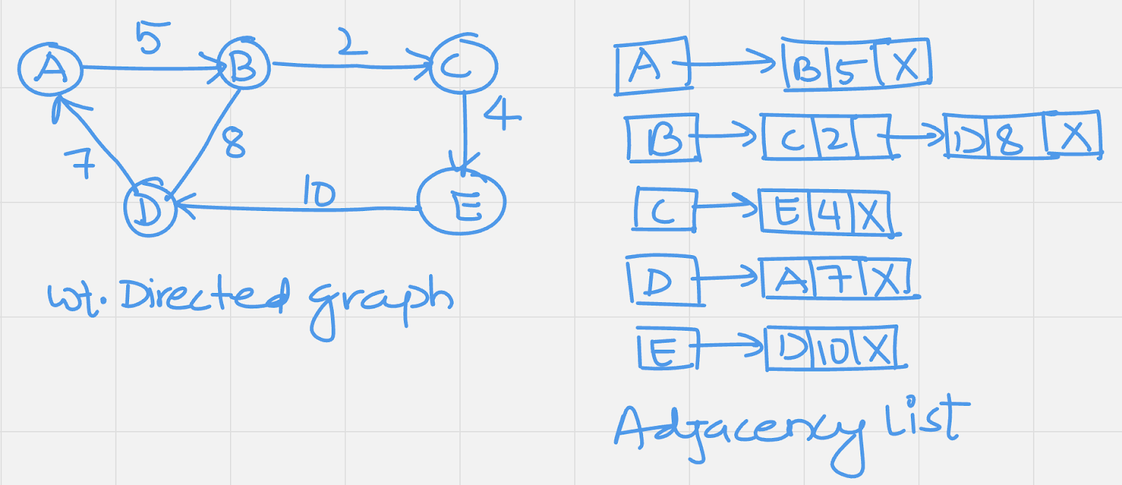
The weighted directed graph along with the adjacency matrix representation is shown in the following figure.
Linked Representation
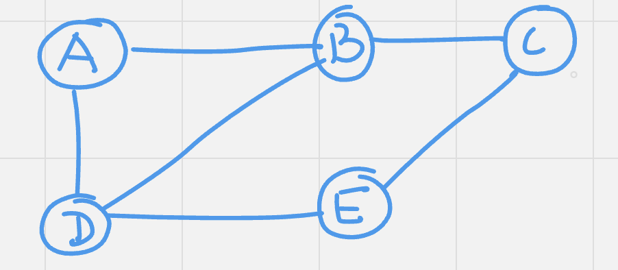
In the linked representation, an adjacency list is used to store the Graph into the computer's memory. Consider the undirected graph shown in the following figure and check the adjacency list representation.
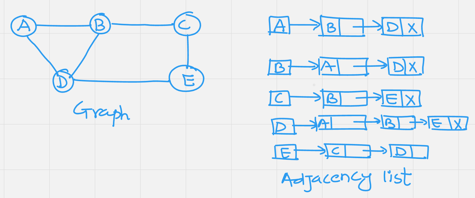
An adjacency list is maintained for each node present in the graph which stores the node value and a pointer to the next adjacent node to the respective node. If all the adjacent nodes are traversed then store the NULL in the pointer field of last node of the list. The sum of the lengths of adjacency lists is equal to the twice of the number of edges present in an undirected graph.
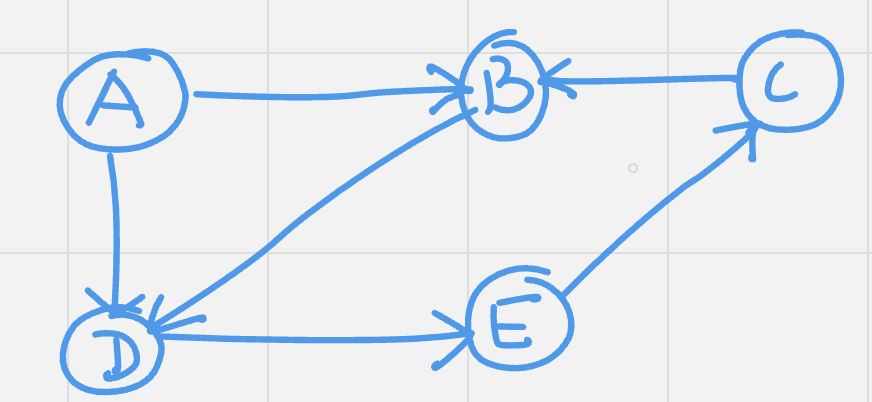
Consider the directed graph shown in the following figure and check the adjacency list representation of the graph.
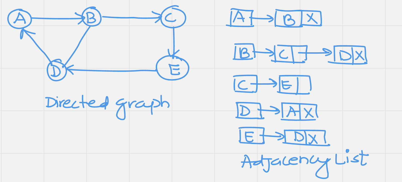
In a directed graph, the sum of lengths of all the adjacency lists is equal to the number of edges present in the graph.
In the case of weighted directed graph, each node contains an extra field that is called the weight of the node. The adjacency list representation of a directed graph is shown in the following figure.