INTERNET INTRANET SOLVED QUESTIONS
- Explain ISPs and how they are interconnected and also explain distinguishing features of a tier-1, tier-2 and tier-3 ISPs.
Internet Service Provider (ISP) is an organization that provides users an access to the Internet by assigning IP addresses. Users are assigned IP addresses by ISP’s. ISPs obtain allocations of IP addresses from a National Internet Registry (NIR) or Local Internet Registry (LIR) or from their appropriate Regional Internet Registry (RIR).
Internet Service Provider (ISP) is an organization that provides users an access to the Internet by assigning IP addresses. ISPs obtain allocations of IP addresses from a National Internet Registry (NIR) or Local Internet Registry (LIR) or from their appropriate Regional Internet Registry (RIR).
In order to exchange traffic directly, two ISPs physically connect in places where they both have facilities, such as in an Internet exchange point. This is usually achieved by linking short wires between routers belonging to one ISP and routers belonging to a second ISP.
The distinguishing feature of following ISPs:
- Tier-1 ISP: These ISPs are at the top of the hierarchy and they have a global reach; they do not pay for any internet traffic through their network; instead lower-tier ISPs have to pay a cost for passing their traffic from one geolocation to another which is not under the reach of that ISPs. ISPs at the same level connect to each other and allow free traffic passes for each other. These ISPs are called peers. Due to this cost is saved. In other words, these ISPs have access to the entire Internet Region routing table solely through its peering relationships. It has a restrictive peering policy. They build infrastructure, such as the Atlantic Internet sea cables, to provide traffic to all other Internet providers, not end users. Example: AT&T, Hibernia Networks etc.
- Tier-2 ISP: These ISPs is a service provider who connects tier 1 and tier 3 ISPs. They have regional or country reach and behave just like Tier-1 ISP for Tier-3 ISP. They have a selective peering policy. Tier 2 ISPs support exchange points. In order to exchange traffic directly via interconnection, two ISPs physically connect in places where they both have facilities, called an internet exchange point. Examples of tier 2 ISPs: Vodafone, Easynet, British Telecom.
- Tier-3 ISP: These ISPs are closest to the end users and help them to connect to the internet by charging some amount. These ISPs work on purchasing models. These ISPs have to pay some cost to Tier-2 ISPs based on traffic generated. Examples of Tier-3, ISPs: World link, Vianet, etc.
2. List advanced features of IPV6. Describe header format and IP datagram fragmentation process in IPv6. Describe internet RFC along with its streams.
The advanced feature of IPV6 are:
- Larger Address Space: In contrast to IPv4, IPv6 uses 4 times more bits to address a device on the Internet. These extra bits can provide approximately 3.4×1038 different combinations of addresses. This address can accumulate the aggressive requirement of address allotment for almost everything in this world. According to an estimate, 1564 addresses can be allocated to every square meter of this earth.
- Simplified Header: IPv6’s header has been simplified by moving all unnecessary information and options (which are present in IPv4 header) to the end of the IPv6 header. IPv6 header is only twice as big as IPv4 provided the IPv6 address is four times longer.
- End-to-end Connectivity: Every system now has a unique IP address and can traverse through the Internet without using NAT or other translating components. After IPv6 is fully implemented, every host can directly reach other hosts on the Internet, with some limitations involved like Firewall, organization policies, etc.
- Auto-configuration: IPv6 supports both stateful and stateless auto configuration mode of its host devices. This way, absence of a DHCP server does not put a halt on inter segment communication.
- Faster Forwarding/Routing: Simplified header puts all unnecessary information at the end of the header. The information contained in the first part of the header is adequate for a Router to take routing decisions, thus making routing decisions as quickly as looking at the mandatory header.
- IPSec: Initially it was decided that IPv6 must have IPSec security, making it more secure than IPv4. This feature has now been made optional.
- No Broadcast: Though Ethernet/Token Ring are considered as broadcast networks because they support Broadcasting, IPv6 does not have any broadcast support any more. It uses multicast to communicate with multiple hosts.
- Anycast Support: This is another characteristic of IPv6. IPv6 has introduced Anycast mode for packet routing. In this mode, multiple interfaces over the Internet are assigned the same Anycast IP address. Routers, while routing, send the packet to the nearest destination.
- Mobility: IPv6 was designed keeping mobility in mind. This feature enables hosts (such as mobile phones) to roam around in different geographical area and remain connected with the same IP address. The mobility feature of IPv6 takes advantage of auto IP configuration and Extension headers.
- Enhanced Priority Support: IPv4 used 6 bits DSCP (Differential Service Code Point) and 2 bits ECN (Explicit Congestion Notification) to provide Quality of Service but it could only be used if the end-to-end devices support it, that is, the source and destination device and underlying network must support it.
In IPv6, Traffic class and Flow label are used to tell the underlying routers how to efficiently process the packet and route it.
- Smooth Transition: Large IP address scheme in IPv6 enables to allocate devices with globally unique IP addresses. This mechanism saves IP addresses and NAT is not required. So devices can send/receive data among each other, for example, VoIP and/or any streaming media can be used much more efficiently.
Another fact is, the header is less loaded, so routers can take forwarding decisions and forward them as quickly as they arrive.
- Extensibility: One of the major advantages of IPv6 header is that it is extensible to add more information in the option part. IPv4 provides only 40-bytes for options, whereas options in IPv6 can be as much as the size of the IPv6 packet itself.
IPV6 Basic Header Format:
An IPv6 basic header is fixed as 40 bytes long and has eight fields. Each IPv6 packet must have an IPv6 basic header that provides basic packet forwarding information, and which all devices parse on the forwarding path.
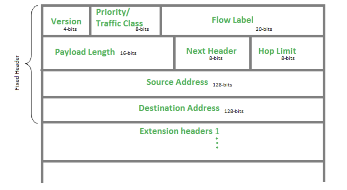
Fig. IPv6 Basic Header Format
- Version (4-bits):
Indicates version of Internet Protocol which contains bit sequence 0110.
- Traffic Class (8-bits):
The Traffic Class field indicates the class or priority of the IPv6 packet which is similar to the Service Field in IPv4 packet. It helps routers to handle the traffic based on priority of the packet. If congestion occurs on the router then packets with least priority will be discarded. As of now only 4-bits are being used (and remaining bits are under research), in which 0 to 7 are assigned to Congestion controlled traffic and 8 to 15 are assigned to Uncontrolled traffic.
Uncontrolled data traffic is mainly used for Audio/Video data. So we give higher priority to uncontrolled data traffic. Source node is allowed to set the priorities but on the way routers can change it. Therefore, the destination should not expect the same priority which was set by the source node.
- Flow Label (20-bits):
Flow Label field is used by source to label the packets belonging to the same flow in order to request special handling by intermediate IPv6 routers, such as non-default quality of service or real time service. In order to distinguish the flow, intermediate router can use source address,
destination address and flow label of the packets. Between a source and destination multiple flows may exist because many processes might be running at the same time. Routers or Host that do not support the functionality of flow label field and for default router handling, flow label field is set to 0. While setting up the flow label, source is also supposed to specify the lifetime of flow.
- Payload Length (16-bits):
It is a 16-bit (unsigned integer) field, indicating total size of the payload which tells routers about amount of information a particular packet contains in its payload. Payload Length field includes extension headers (if any) and upper layer packet. In case length of payload is greater than 65,535 bytes (payload up to 65,535 bytes can be indicated with 16-bits), then the payload length field will be set to 0 and jumbo payload option is used in the Hop-by-Hop options extension header.
- Next Header (8-bits):
Next Header indicates the type of extension header (if present) immediately following the IPv6 header. Whereas In some cases it indicates the protocols contained within upper-layer packet, such as TCP, UDP.
- Hop Limit (8-bits):
Hop Limit field is same as TTL in IPv4 packets. It indicates the maximum number of intermediate nodes IPv6 packet is allowed to travel. Its value gets decremented by one, by each node that forwards the packet and packet is discarded if value decrements to 0. This is used to discard the packets that are stuck in infinite loop because of some routing error.
- Source Address (128-bits):
Source Address is 128-bit IPv6 address of the original source of the packet.
- Destination Address (128-bits):
Destination Address field indicates the IPv6 address of the final destination (in most cases). All the intermediate nodes can use this information in order to correctly route the packets
IPv6 Extension Headers:
An IPv4 packet header has an optional field (Options), which includes security, timestamp, and record route options. The variable length of the Options field makes the IPv4 packet header length range from 20 bytes to 60 bytes. When devices forward IPv4 packets with the Options field, many resources need to be used. Therefore, these IPv4 packets are rarely used in practice.
To improve packet processing efficiency, IPv6 uses extension headers to replace the Options field in the IPv4 header. Extension headers are placed between the IPv6 basic header and upper- layer PDU. An IPv6 packet may carry zero or more extension headers. The sender of a packet adds one or more extension headers to the packet only when the sender requests the destination device or other devices to perform special handling. Unlike IPv4, IPv6 has variable-length extension headers, which are not limited to 40 bytes. This facilitates further extension. To improve extension header processing efficiency and transport protocol performance, IPv6 requires that the extension header length be an integer multiple of 8 bytes.
When multiple extension headers are used, the Next Header field of an extension header indicates the type of the next header following this extension header. The Next Header field in the IPv6 basic header indicates the type of the first extension header, and the Next Header field in the first extension header indicates the type of the next extension header. If there are no extension
headers following the current one, the Next Header field indicates the upper-layer protocol type. Figure below shows the IPv6 extension header format.
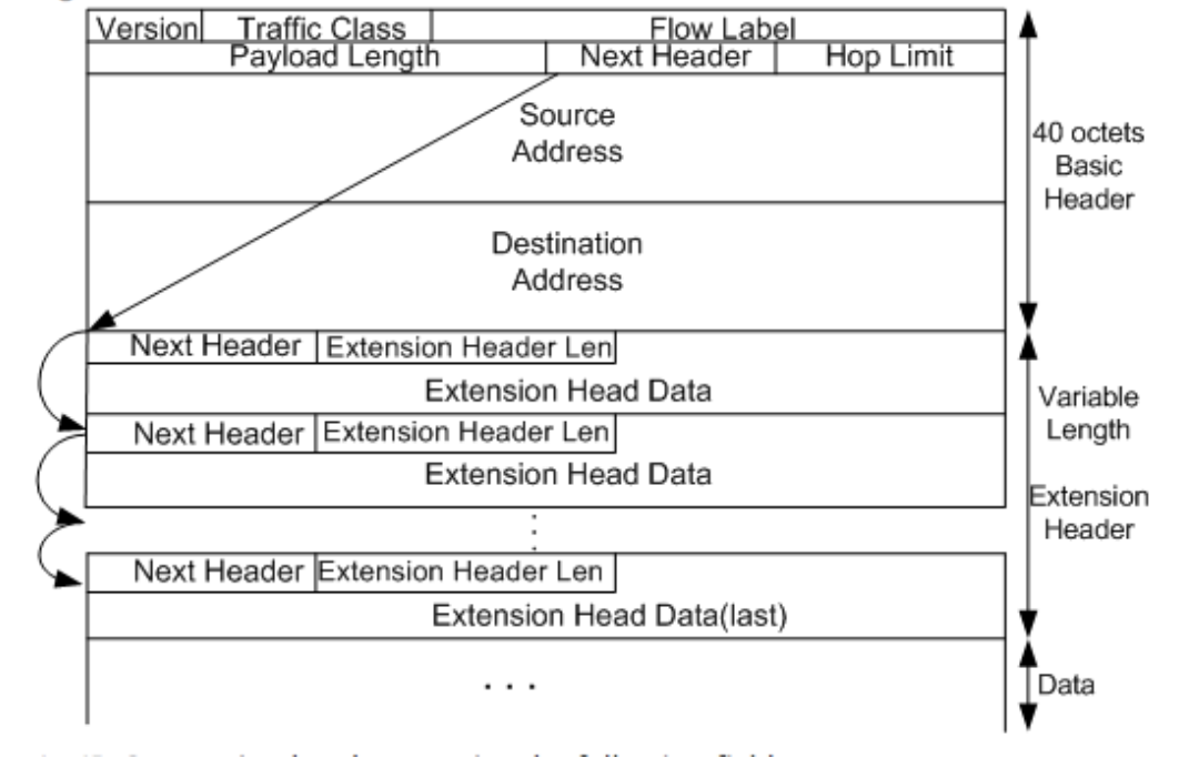
An IPv6 extension header contains the following fields:
- Next Header: 8 bits long. This is similar to the Next Header field in the IPv6 basic header, indicating the type of the next extension header (if any) or the upper-layer protocol type.
- Extension Header Len: 8 bits long. This indicates the extension header length excluding the Next Header field.
- Extension Head Data: Variable length. This includes a series of options and the padding field.
Internet RFCs with its streams
A Request for Comments (RFC) is a publication from the Internet Society (ISOC) and its associated bodies, most prominently the Internet Engineering Task Force (IETF), the principal technical development and standards-setting bodies for the Internet.
An RFC is authored by individuals or groups of engineers and computer scientists in the form of a memorandum describing methods, behaviors, research, or innovations applicable to the working of the Internet and Internet-connected systems. It is submitted either for peer review or to convey new concepts, information, or occasional engineering humor.
The IETF adopts some of the proposals published as RFCs as Internet Standards. However, many RFCs are informational or experimental in nature and are not standards.The RFC system was invented by Steve Crocker in 1969 to help record unofficial notes on the development of ARPANET. RFCs have since become official documents of Internet specifications, communications protocols, procedures, and events.
There are four streams of RFCs:
• IETF:
The Internet Engineering Task Force (IETF) is an open standards organization, which develops and promotes voluntary Internet standards, in particular the standards that comprise the Internet protocol suite (TCP/IP). It has no formal membership roster or membership requirements. All participants and managers are volunteers, though their work is usually funded by their employers or sponsors. The IETF is organized into a large number of working groups and birds of a feather informal discussion groups, each dealing with a specific topic. The IETF operates in a bottom-up task creation mode, largely driven by these working groups each of which has an appointed chairperson or co-chairs, a charter to describe its focus and what and when it is expected to produce. The basic mechanism of IETF is publication of proposed specifications, development based on the proposals, review and independent testing by participants, and republication as a revised proposal, a draft proposal, or eventually as an Internet Standard. All IETF documents are freely available over the Internet and can be reproduced at will. The IETF cooperates with the W3C, ISO/IEC, ITU, and other standards bodies.
- IRTF:
The Internet Research Task Force (IRTF) focuses on longer-term research issues related to the Internet while the parallel organization, the Internet Engineering Task Force (IETF), focuses on the shorter term issues of engineering and standards making. The Internet Research Task Force (IRTF) promotes research of importance to the evolution of the Internet by creating focused, long- term research groups working on topics related to Internet protocols, applications, architecture and technology. The IRTF is managed by the IRTF chair in consultation with the Internet Research Steering Group (IRSG) which includes the IRTF chair, the chairs of the various Research Groups and other individuals (members at large) from the research community selected by the IRTF chair. The IRTF chair is responsible for ensuring that research groups produce coherent, coordinated, architecturally consistent and timely output as a contribution to the overall evolution of the Internet architecture. In addition to the detailed tasks related to research groups outlined below, the IRTF chair may also from time to time arrange for topical workshops attended by the IRSG and perhaps other experts in the field.
- IAB:
The Internet Architecture Board (IAB) is "a committee of the Internet Engineering Task Force (IETF) and an advisory body of the Internet Society (ISOC). Its responsibilities include Internet Standards Process oversight and appeal, architectural oversight of Internet protocols, liaising with other organizations on behalf of IETF, selection and appointment of IETF chair and area directors and IRTF chairs and the appointment of the Request for Comments (RFC) Editor. The IAB is also responsible for the management of the IETF protocol parameter registries and Internet standards documents (RFC series). It acts as source of advice and guidance to the Internet Society.
- Other independent submission
3. Explain different types of proxy array load balancing mechanism and also explain in detail which mechanism is appropriate for big ISPs.
Load balancing is a computer networking methodology to distribute workload across multiple computers or a computer cluster, network links, central processing units, disk drives, or other resources, to achieve optimal resource utilization, maximize throughput, minimize response time, and avoid overload. Proxy server is a server that acts as an intermediate between requests from clients seeking resources from other servers. Proxy array load balancing means a load balancing technique where multiple proxy servers operate as a single cache for client requests.
There are different types of proxy array load balancing mechanism which are described below:
- Random Allocation: In a random allocation, the HTTP requests are assigned to any server picked randomly among the group of servers. In such a case, one of the servers may be assigned many more requests to process, while the other servers are sitting idle. However, on average, each server gets its share of the load due to the random selection.
- DNS Round Robin: DNS RR is a simple technique of load balancing various Internet services such as Web server, e-mail server by creating multiple DNS A records with the same name. In it, DNS is configured such a way that multiple IP Addresses correspond to a single host name. In other words, all clients would receive service from multiple different server, thus distributing the overall load among servers. Better versions:
- Weighted Round-Robin: server of higher capacity gets higher weight
- Dynamic Round-Robin: Weights are based on continuous monitoring of servers and so ever changing
- Internet Cache Protocol (ICP): The Internet Cache Protocol (ICP) is an object location protocol that enables caches to communicate with one another. Caches can use ICP to send queries and replies about the existence of cached URLs and about the best locations from which to retrieve those URLs. In a typical ICP exchange, one cache will send an ICP query about a particular URL to all neighboring caches. Those caches will then send back ICP replies that indicate whether they contain that URL. If the caches do not contain the URL, they send back miss. If they do contain the URL, they send back hit. It is typically used by proxy servers to check other proxy server’s cache for the purpose of finding out the most appropriate location to retrieve a requested object from in the situation where multiple caches are in use at a single site.
- Cache Array Routing Protocol (CARP): It is a non-redundant proxy load balancing mechanism. CARP is a hash-based proxy selection mechanism. It uses hashing to select the server. So, there is no necessity of queries. It automatically adjusts for the addition or deletion of the server. It eliminates the cache redundancy. Hence, this mechanism is suitable for big ISPs. It’s working is as follows:
- Assume an array of Proxy servers and array membership is tracked using membership list.
- A hash value Hs is computed for the name of each proxy server in the list.
- A hash value Hu is computed for the name of each requested URL.
- For each request, a combined hash value Hc = F(Hs , Hu) is computed for all the servers.
- The server with the highest value of Hc for a requested URL is selected. Several benefits are provided by CARP which makes it suitable for larger ISPs:
- It saves network bandwidth by avoiding the query messaging between proxy servers.
It eliminates the duplication of content that occurs when proxy servers are grouped in arrays, resulting in faster response times and more efficient use of server resources.
Highly scalable
No new protocols are required
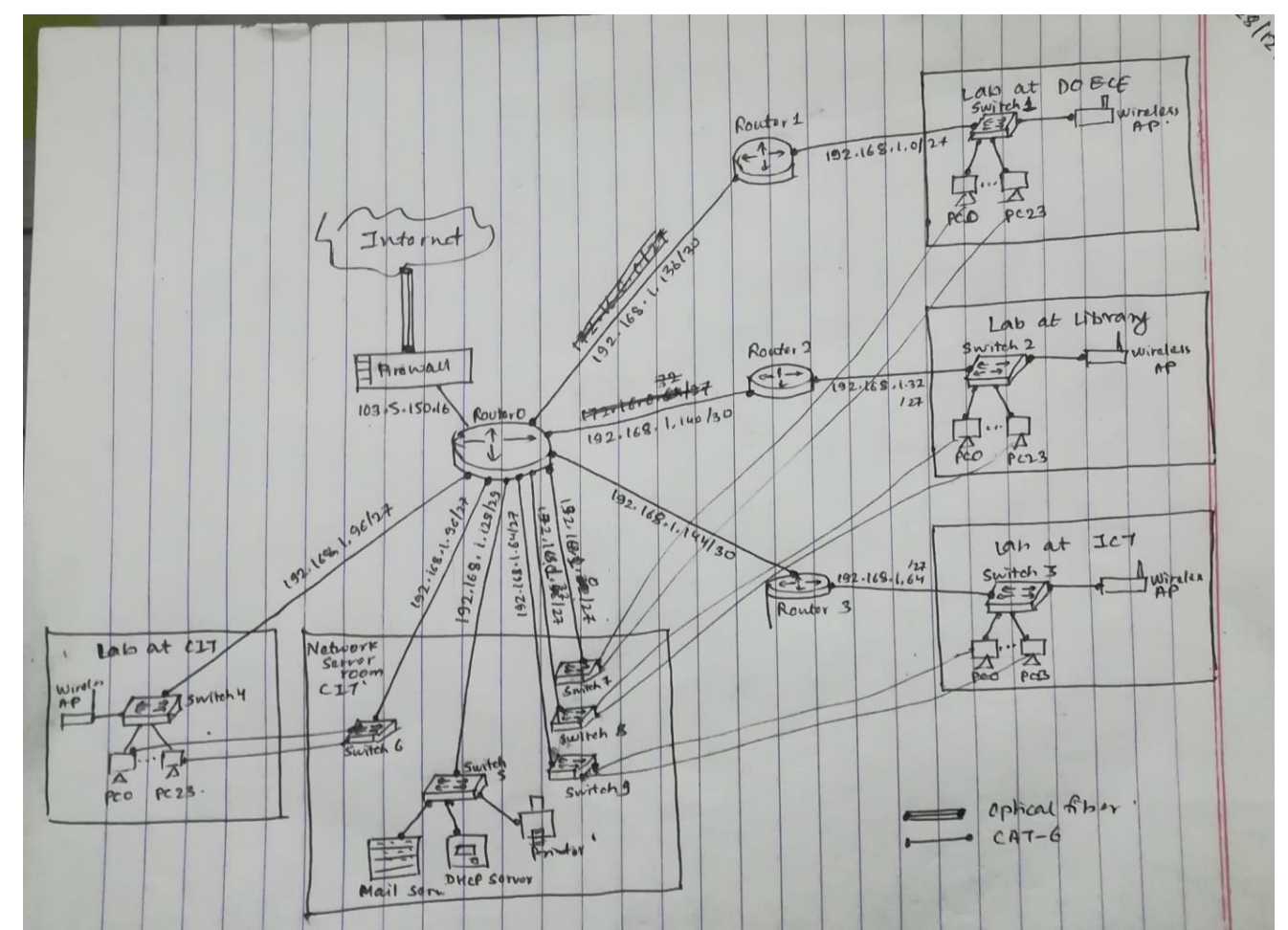
- DOECE has 4 computer labs each having 24 computers. One lab is located at ground floor of library building, one is at ground floor of CIT building, one at first floor of DOECE building and one research lab is at third floor of ICT building. Each computer has redundant network connection via dual port CAT6 information outlet connected directly from the network server room which is on the first floor of CIT building. Prepare Bill of Quantity (BOQ) with necessary network resources required in quality for complete networking. Your BOQ should include estimation of information outlet (faceplate), wireless AP, CAT6 cables, patch cords, 24-ports patch panel and 24 port switches. Include logical IP addressing in each computer in each lab with an address assigned by DHCP Server (in server room) which has one dedicated IP address for DOECE building. Assume IP address as your own.
Along with all the devices mentioned above, we’ve assumed there is one access point in each lab and FTP, Mail Server along with a printer in the server room. Each building also has one router.
Physical devices required:
- Routers
- Switches
- CAT6 cable
- Fiber optic cable
- PCs/ Laptop/Workstation
- Printer
- Servers: Mail Server, DHCP Server
- Wireless APs
First, we will logically design the network topology as per the requirement then bill of quantity will be made.
We have assumed that the dedicated IP address is 103.5.150.16 and NAT has been used so that each network interface can have its own (private) IP. We assign private IP addresses from the class C range, the address assumed is 192.168.1.0/24.
Subnetting is required, VLSM will be used.
For each lab, there are 25 hosts so 5 bits is enough as it can support a maximum of (32-2)=30 hosts.
Subnetting and IP assignment for 4 labs
|
Lab/room |
Network IP address |
Broadcast IP address |
Number of addressable hosts |
|
Lab at DOECE building |
192.168.1.0/27 |
192.168.1.31/27 |
30 hosts (192.168.1.1 to 192.168.1.30) |
|
Lab at library building |
192.168.1.32/27 |
192.168.1.63/27 |
30 hosts (192.168.1.33 to 192.168.1.62) |
|
Lab at ICT building |
192.168.1.64/27 |
192.168.1.95/27 |
30 hosts (192.168.1.65 to 192.168.1.94) |
|
Lab at CIT building |
192.168.1.96/27 |
192.168.1.127/27 |
30 hosts (192.168.1.97 to 192.168.1.126) |
For our network server room, we need 3 hosts so 3 bits is enough as it can support a maximum of (8-2)=6 hosts. So the host part would be of 3 bits.
|
Room |
Network IP address |
Broadcast IP address |
Number of addressable hosts |
|
Network Server Room (CIT) |
192.168.1.128/29 |
192.168.1.135/29 |
6 hosts (192.168.1.129 to 192.168.1.135) |
For interconnection of Router 0 with routers 1, 2 and 3. Only 2 IPs are needed so 2 bits is enough. Host part of 2 bits and mask /30
|
Routers connected |
Network IP address |
Broadcast IP address |
Number of addressable hosts |
|
Router 1 (DOECE) <-> Router 0 |
192.168.1.136/30 |
192.168.1.139/30 |
2 hosts (192.168.1.137 and 192.168.1. 138) |
|
Router 2 (Library) <-> Router 0 |
192.168.1.140/30 |
192.168.1.143/30 |
2 hosts (192.168.1.141 and 192.168.1.142) |
|
Router 3 (ICT) <-> Router 0 |
192.168.1.144/30 |
192.168.1.147/30 |
2 hosts (192.168.1.145 and 192.168.1. 146) |
Specification Sheet / Bill Of Quantity
|
SN |
Item Description |
Quantity |
Units |
Summary Specification |
|
1 |
Router |
4 |
Pcs |
Variable specification; One at least must be capable of NAT. |
|
2 |
Switch |
9 |
Pcs |
24-port switch Cisco 2950-24 |
|
3 |
Firewall |
1 |
Pcs |
Varying Specs |
|
4 |
PCs |
96 |
Pcs |
Varying Specs |
|
5 |
Wireless AP |
4 |
Pcs |
50Mbps, Wireless N Router; 2.4 - |
|
2.4835GHz |
||||
|
6 |
Optic fiber cable |
500 |
m |
Provided by ISP |
|
7 |
CAT 6 UTP cable |
212 |
Pcs |
4-pair pure copper conductor PVC jacketed Foiled/UTP cable with TIA standard color 23AWG and having tested frequency range of 250-550 MHz, Support up to 1000Base-T at 100 meters |
|
8 |
Server Computer |
3 |
Pcs |
Mail server, FTP server, DHCP server |
|
9 |
Printer |
1 |
Pcs |
Varying Specs |
A figure of the intranet designed is given below:
5. Explain different types of virtual hosting with examples. Write down major steps while configuring the name based virtual hosting.
Virtual hosting is a method for hosting multiple domain names (with separate handling of each name) on a single server (or pool of servers). This allows one server to share its resources, such as memory and processor cycles, without requiring all services provided to use the same host name. The term virtual hosting is usually used in reference to web servers but the principles do carry over to other Internet services.
There are two main types of virtual hosting, name-based and IP-based:
- Name-based virtual hosting uses the host name presented by the client. This saves IP addresses and the associated administrative overhead but the protocol being served must supply the host name at an appropriate point. In particular, there are significant difficulties using name-based virtual hosting with SSL/TLS. The biggest issue with name-based virtual hosting is that it is difficult to host multiple secure websites running SSL/TLS. Because the SSL/TLS handshake takes place before the expected hostname is sent to the server, the server doesn't know which certificate to present in the handshake. It is possible for a single certificate to cover multiple names either through the "subjectaltname" field or through wildcards but the practical application of this approach is limited by administrative considerations and by the matching rules for wildcards. For example: a server could be receiving requests for two domains, www.abc.com and www.bac.org, both of which resolve to the same IP address as configured in DNS. For www.abc.com, the server could send the HTTP file from the directory
/var/www/user/abc/site/, while request for www.bac.org, would make the server serve pages from /var/www/user/bac/site/.
- IP-based virtual hosting uses a separate IP address for each host name, and it can be performed with any protocol but requires a dedicated IP address per domain name served. Port-based virtual hosting is also possible in principle but is rarely used in practice because it is unfriendly to users. The downside of this approach is the server needs a different IP address for every web site. This increases administrative overhead (both assigning addresses to servers and justifying the use of those addresses to internet registries) and contributes to IPv4 address exhaustion.
For example: a server has two IPs 192.168.100.2 and 192.168.100.1 both listening to the same port. Then when a client makes request to 192.168.100.2, the server would send HTTP file from directory /var/www/user/two/site/ and for 192.168.100.1, the server would send HTTP file from directory /var/www/user/one/site/.
The major steps while configuring name based virtual hosting are listed below:
- Create document root for two or more domain names. Generally, these folders have to be kept in the /var/www/html folder. For the rest of these steps, say we have created folders/var/www/html/www.bob.com and /var/www/html/www.alice.com with an index.html in both.
- Create server configuration files for the websites in corresponding .conf files and add all the virtual host with corresponding IP address, document root and server name as follows:
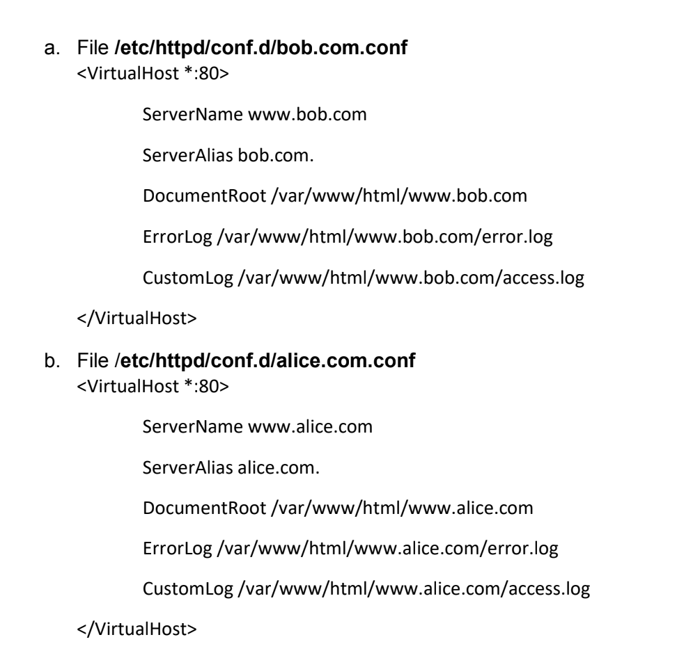
3. Restart the server for changes to take effect.
Say in a centos environment where Apaches process is called httpd
sudo systemctl restart httpd
6. Write short notes on:
- WYSIWYG
WYSIWYG, an acronym for What You See Is What You Get, is a system in which editing software allows content to be edited in a form that resembles its appearance when printed or displayed as a finished product, such as a printed document, web page, or slide presentation. WYSIWYG implies a user interface that allows the user to view something very similar to the end result— while the document is being created. In general, WYSIWYG implies the ability to directly manipulate the layout of a document without having to type or remember names of layout commands.
The first true WYSIWYG editor was a word processing program called Bravo. Invented by Charles Simonyi at the Xerox Palo Alto Research Center in the 1970s, it became the basis for Simonyi's work at Microsoft and evolved into two other WYSIWYG applications called Word and Excel. An HTML WYSIWYG editor, such as Microsoft's FrontPage or Adobe's PageMill conceals the markup and allows the Web page developer to think entirely in terms of how the content should appear. Other common usages of WYSIWYG are programs that allow user to manipulate 3D models in stereo-chemistry, computer-aided design, and 3D computer graphics.
b. XML
Extensible Markup Language (XML) is a simple, very flexible text format derived from SGML (ISO 8879). The design goals of XML emphasize simplicity, generality, and usability across the Internet. It is a textual data format with strong support via Unicode for different human languages. Although the design of XML focuses on documents, the language is widely used for the representation of arbitrary data structures such as those used in web services.
XML tags identify the data and are used to store and organize the data, rather than specifying how to display it like HTML tags, which are used to display the data. XML is not going to replace HTML in the near future, but it introduces new possibilities by adopting many successful features of HTML.
There are three important characteristics of XML that make it useful in a variety of systems and solutions −
- XML is extensible − XML allows you to create your own self-descriptive tags, or language, that suits your application.
- XML carries the data, does not present it − XML allows you to store the data irrespective of how it will be presented.
- XML is a public standard − XML was developed by an organization called the World Wide Web Consortium (W3C) and is available as an open standard.
- DHCP
Dynamic Host Configuration Protocol (DHCP) is a client/server protocol that automatically provides an Internet Protocol (IP) host with its IP address and other related configuration information such as the subnet mask and default gateway. RFCs 2131 and 2132 define DHCP as an Internet Engineering Task Force (IETF) standard based on Bootstrap Protocol (BOOTP), a protocol with which DHCP shares many implementation details. DHCP allows hosts to obtain required TCP/IP configuration information from a DHCP server.
Every device on a TCP/IP-based network must have a unique unicast IP address to access the network and its resources. Without DHCP, IP addresses for new computers or computers that are moved from one subnet to another must be configured manually; IP addresses for computers that are removed from the network must be manually reclaimed. With DHCP, this entire process is automated and managed centrally. The DHCP server maintains a pool of IP addresses and leases an address to any DHCP-enabled client when it starts up on the network. Because the IP addresses are dynamic (leased) rather than static (permanently assigned), addresses no longer in use are automatically returned to the pool for reallocation.
DHCP provides the following benefits.
- Reliable IP address configuration.
- Reduced network administration. DHCP includes the following features to reduce network administration:
- Centralized and automated TCP/IP configuration.
- The ability to define TCP/IP configurations from a central location.
- The ability to assign a full range of additional TCP/IP configuration values by means of DHCP options.
d. The efficient handling of IP address changes for clients that must be updated frequently, such as those for portable devices that move to different locations on a wireless network.
The forwarding of initial DHCP messages by using a DHCP relay agent, which eliminates the need for a DHCP server on every subnet.
- AJAX
Ajax (short for "Asynchronous JavaScript and XML") is a set of web development techniques using many web technologies on the client side to create asynchronous web applications. With Ajax, web applications can send and retrieve data from a server asynchronously (in the background) without interfering with the display and behaviour of the existing page. By decoupling the data interchange layer from the presentation layer, Ajax allows web pages and, by extension, web applications, to change content dynamically without the need to reload the entire page. In practice, modern implementations commonly utilize JSON instead of XML.
Ajax is not a single technology, but rather a group of technologies. HTML and CSS can be used in combination to mark up and style information. AJAX just uses a combination of:
- A browser built-in XMLHttpRequest object (to request data from a web server)
- JavaScript and HTML DOM (to display or use the data)
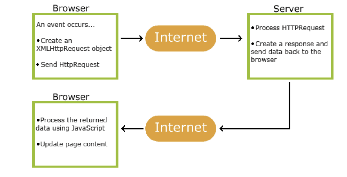
Fig. How AJAX works Step-by-step process of how AJAX works:
- An event occurs in a web page (the page is loaded, a button is clicked)
- An XMLHttpRequest object is created by JavaScript
- The XMLHttpRequest object sends a request to a web server
- The server processes the request
- The server sends a response back to the web page
6. The response is read by JavaScript
Proper action (like page update) is performed by JavaScript
- Email Agents and their function
An email agent is a program that is part of the email infrastructure, from composition by sender, to transfer across the network, to viewing by recipient. The best-known are mail user agents (MUAs, aka, email clients) and mail transfer agents (MTAs, programs that transfer email between clients), but finer divisions exist.
Email servers are built from one or more software packages, each of which carries out the functions of one or more MxA.
The three main types of Email agents, along with their respective functions are:
- Mail User Agent (MUA): is an application (e.g., Outlook Express, Thunderbird) that runs on a user's computer. Mail user agents are used to compose and send messages, as well as to display and manage messages in a user's mailbox.
- Mail transfer agents (MTA): are used to pass emails between different mail servers. When a mail user agent passes a message to a mail transfer agent, the latter passes the message to another transfer agent (or possibly many other transfer agents). Transfer agents are responsible for properly routing messages to the destination.
- Mail delivery agents (MDA): are used to place messages into a local user's mailbox. When the message arrives at its destination, the final transfer agent gives the message to the appropriate delivery agent, and the latter delivers the message to the user's mailbox