Representation of System Behavior
Introduction
A system sequence diagram is a fast and easily created artifact that illustrates input and output events related to the systems under discussion. The UML contains notation in the form of sequence diagrams to illustrate events from external actors to a system.
System Behavior
Before proceeding to a logical design of how a software application will work, it is useful to investigate and define its behavior as a "black box." System behavior is a description of what a system does, without explaining how it does it. One part of that description is a system sequence diagram.
System Sequence Diagrams
Use cases describe how external actors interact with the software system we are interested in creating. During this interaction an actor generates events to a system, usually requesting some operation in response. For example, when a cashier enters an item's ID, the cashier is requesting the POS system to record that item's sale. That request event initiates an operation upon the system. It is desirable to isolate and illustrate the operations that an external actor requests of a system, because they are an important part of understanding system behavior. The UML includes sequence diagrams as a notation that can illustrate actor interactions and the operations initiated by them. A system sequence diagram (SSD) is a picture that shows, for a particular scenario of a use case, the events that external actors generate, their order, and inter-system events. All systems are treated as a black box; the emphasis of the diagram is events that cross the system boundary from actors to systems.
The UML does not define something called a "system" sequence diagram, but simply a sequence diagram. The qualification is used to emphasize its application to systems as black boxes.
Example of an SSD
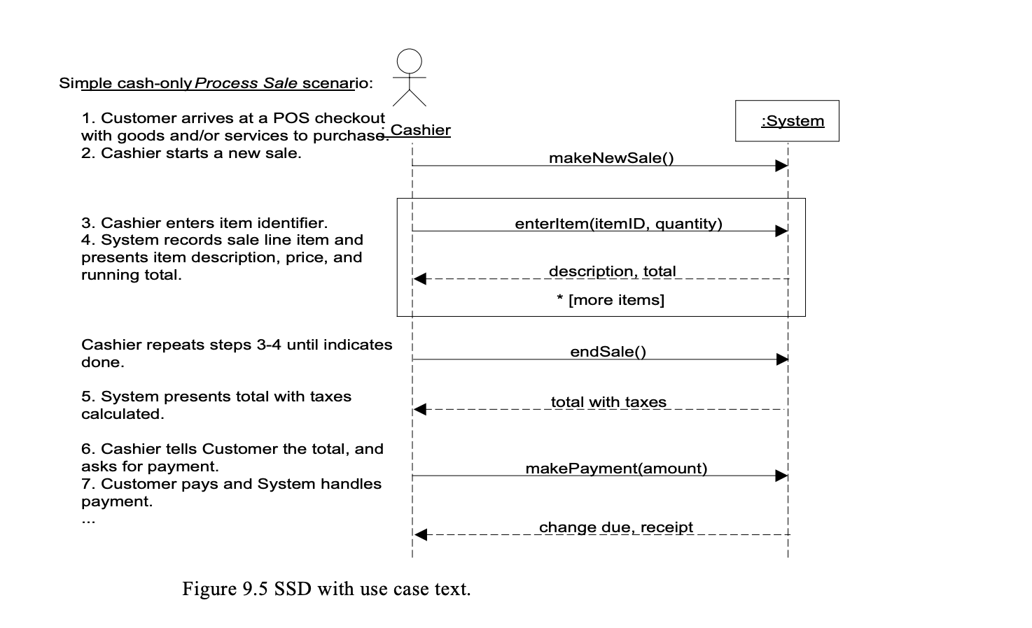
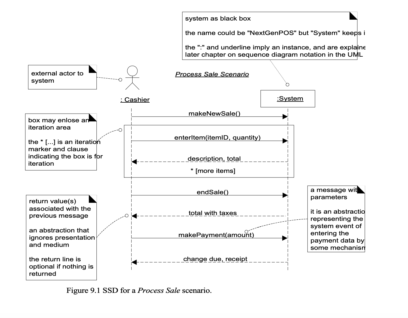
An SSD shows, for a particular course of events within a use case, the external actors that interact directly with the system, the system (as a black box), and the system events that the actors generate (see Figure 9.1). Time proceeds downward, and the ordering of events should follow their order in the use case. System events may include parameters. This example is for the main success scenario of the Process Sale use case. It indicates that the cashier generates makeNewSale, enteritem, endSale, and makePayment system events.
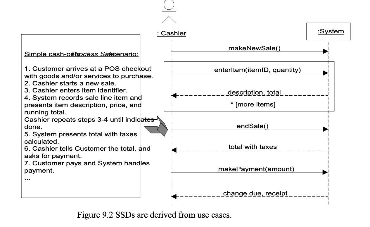
SSDs and Use Cases
An SSD shows system events for a scenario of a use case, therefore it is generated from inspection of a use case:
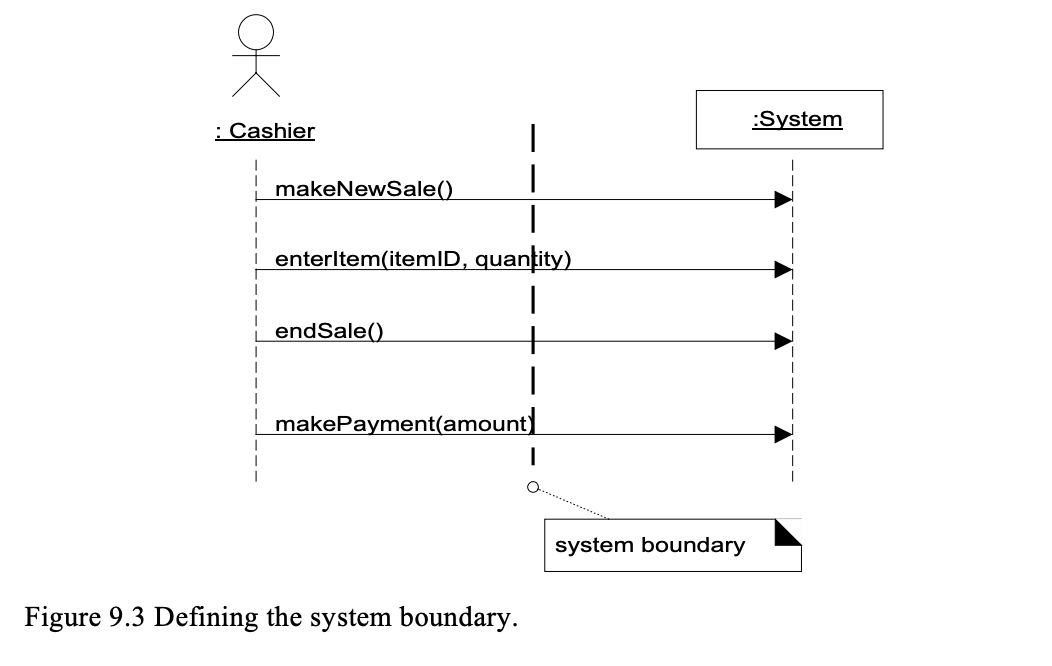
System Events and the System Boundary
To identify system events, it is necessary to be clear on the choice of system boundary, as discussed in the prior chapter on use cases. For the purposes of software development, the system boundary is usually chosen to be the software (and possibly hardware) system itself; in this context, a system event is an external event that directly stimulates the software (see Figure 9.3).
Consider the Process Sale use case to identify system events. First, we must determine the actors that directly interact with the software system. The customer interacts with the cashier, but for this simple cash-only scenario, does not directly interact with the POS system—only the cashier does. Therefore, the customer is not a generator of system events; only the cashier is.
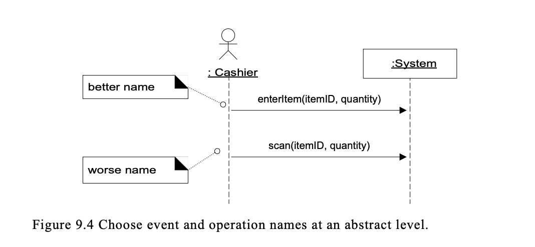
Naming System Events and Operations
Thus "enteritem" is better than "scan" (that is, laser scan) because it captures the intent of the operation while remaining abstract and noncommittal with respect to design choices about what interface is used to capture the system event.
SSDs and the Glossary
The terms shown in SSDs (operations, parameters, return data) are terse. These may need proper explanation so that during design work it is clear what is coming in and going out. If this was not explicated in the use cases, the Glossary could be used. However, as always when discussing the creation of artifacts other than code (the heart of the project), be suspicious. There should be some truly meaningful use or decision made with the Glossary data, otherwise it is simply low-value unnecessary work.