Overview of UML: UML fundamentals and notations
Unified Modeling Language:
UML is a notation that resulted from the unification of OMT (Object Modeling Technique [Rumbaugh et al., 1991]), Booch [Booch, 1994], and OOSE (Object-Oriented Software Engineering [Jacobson et al., 1992]). UML has also been influenced by other object-oriented notations, such as those introduced by Mellor and Shlaer [Mellor & Shlaer, 1998], Coad and Yourdon [Coad et al., 1995], Wirfs-Brock [Wirfs-Brock et al., 1990], and Martin and Odell [Martin & Odell, 1992].
The goal of UML is to provide a standard notation that can be used by all object-oriented methods and to select and integrate the best elements of precursor notations. For example, UML includes the use case diagrams introduced by OOSE and uses many features of the OMT class diagrams. UML also includes new concepts that were not present in other major methods at the time, such as extension mechanisms and a constraint language. UML has been designed for a broad range of applications. Hence, it provides constructs for a broad range of systems and activities (e.g., distributed systems, analysis, system design, deployment).
System development focuses on three different models of the system:
- The functional model, represented in UML with use case diagrams, describes the functionality of the system from the user’s point of view.
- The object model, represented in UML with class diagrams, describes the structure of the system in terms of objects, attributes, associations, and operations. During requirements and analysis, the object model starts as the analysis object model and describes the application concepts relevant to the system. During system design, the object model is refined into the system design object model and includes descriptions of the subsystem interfaces. During object design, the object model is refined into the object design model and includes detailed descriptions of solution objects.
- The dynamic model, represented in UML with interaction diagrams, state machine diagrams, and activity diagrams, describes the internal behavior of the system. Interaction diagrams describe behavior as a sequence of messages exchanged among a set of objects, whereas state machine diagrams describe behavior in terms of states of an individual object and the possible transitions between states. Activity diagrams describe behavior in terms of control and data flows.
An Overview of UML
The five UML notations:
- Use Case Diagrams-
- Class Diagrams
- Interaction Diagrams
- State Machine Diagrams
- Activity Diagrams
Use Case Diagrams
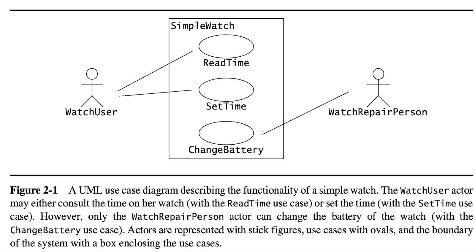
Use cases are used during requirements elicitation and analysis to represent the functionality of the system. Use cases focus on the behavior of the system from an external point of view. A use case describes a function provided by the system that yields a visible result for an actor. An actor describes any entity that interacts with the system (e.g., a user, another system, the system’s physical environment). The identification of actors and use cases results in the definition of the boundary of the system, that is, in differentiating the tasks accomplished by the system and the tasks accomplished by its environment. The actors are outside the boundary of the system, whereas the use cases are inside the boundary of the system.
For example, Figure 2-1 depicts a use case diagram for a simple watch. The WatchUser actor may either consult the time on their watch (with the ReadTime use case) or set the time (with the SetTime use case). However, only the WatchRepairPerson actor can change the battery of the watch (with the ChangeBattery use case).
Class Diagrams
Class diagrams are used to describe the structure of the system. Classes are abstractions that specify the common structure and behavior of a set of objects. Objects are instances of classes that are created, modified, and destroyed during the execution of the system. An object has state that includes the values of its attributes and its links with other objects.
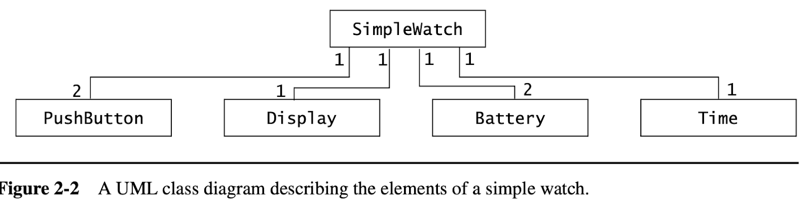
Class diagrams describe the system in terms of objects, classes, attributes, operations, and their associations. For example, Figure 2-2 is a class diagram describing the elements of all the watches of the SimpleWatch class. These watch objects all have an association to an object of the PushButton class, an object of the Display class, an object of the Time class, and an object of the Battery class. The numbers on the ends of associations denote the number of links each SimpleWatch object can have with an object of a given class. For example, a SimpleWatch has exactly two PushButtons, one Display, two Batteries, and one Time. Similarly, all PushButton, Display, Time, and Battery objects are associated with exactly one SimpleWatch object.
Interaction Diagrams
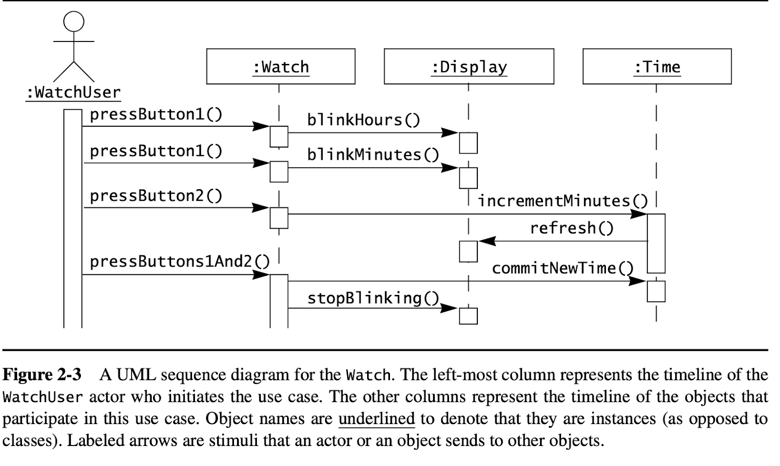
Interaction diagrams are used to formalize the dynamic behavior of the system and to visualize the communication among objects. They are useful for identifying additional objects that participate in the use cases. We call objects involved in a use case participating objects. An interaction diagram represents the interactions that take place among these objects. For example, Figure 2-3 is a special form of interaction diagram, called a sequence diagram, for the SetTime use case of our simple watch. The left-most column represents the WatchUser actor who initiates the use case. Labeled arrows represent stimuli that an actor or an object sends to other objects. In this case, the WatchUser presses button 1 twice and button 2 once to set her watch a minute ahead. The SetTime use case terminates when the WatchUser presses both buttons simultaneously.
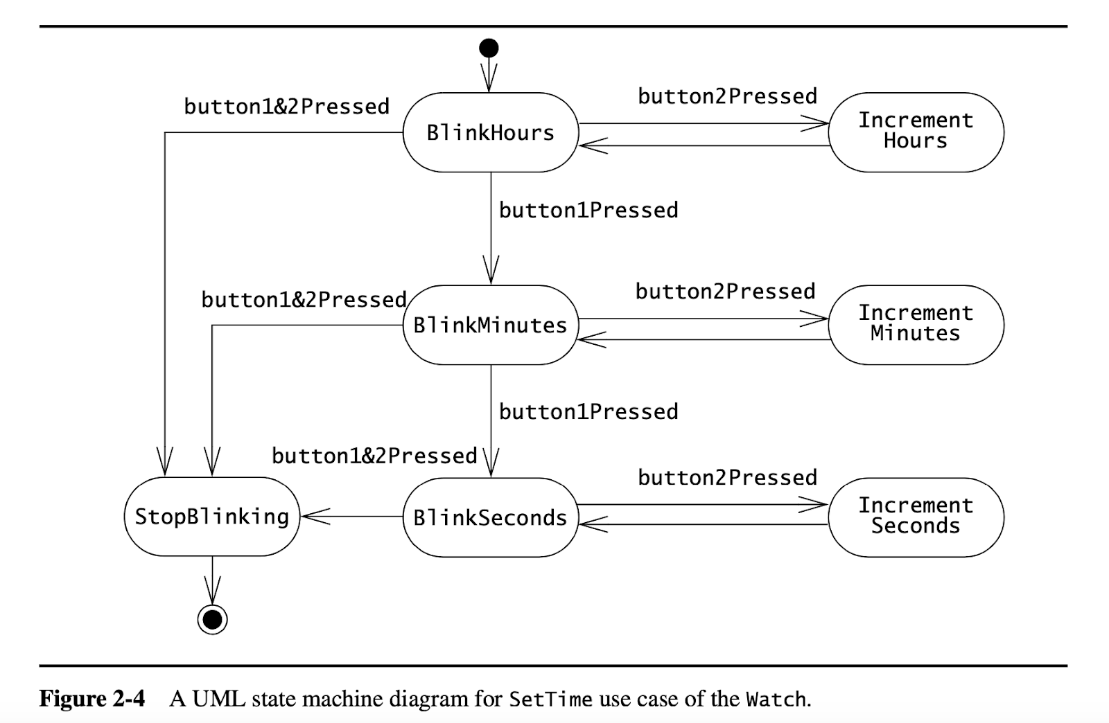
State Machine Diagrams
State machine diagrams describe the dynamic behavior of an individual object as a number of states and transitions between these states. A state represents a particular set of values for an object. Given a state, a transition represents a future state the object can move to and the conditions associated with the change of state. For example, Figure 2-4 is a state machine diagram for the Watch. A small black circle initiates that BlinkHours is the initial state. A circle surrounding a small black circle indicates that StopBlinking is a final state. Note that this diagram represents different information than the sequence diagram of Figure 2-3. The sequence diagram focuses on the messages exchanged between objects as a result of external events created by actors. The state machine diagram focuses on the transitions between states as a result of external events for an individual object.
Activity Diagrams
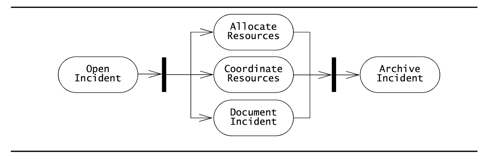
An activity diagram describes the behavior of a system in terms of activities. Activities are modeling elements that represent the execution of a set of operations. The execution of an activity can be triggered by the completion of other activities, by the availability of objects, or by external events. Activity diagrams are similar to flowchart diagrams in that they can be used to represent control flow (i.e., the order in which operations occur) and data flow (i.e., the objects that are exchanged among operations). For example, Figure 2-5 is an activity diagram representing activities related to managing an Incident. Rounded rectangles represent activities; arrows between activities represent control flow; thick bars represent the synchronization of the control flow. The activity diagram of Figure 2-5 depicts that the AllocateResources, CoordinateResources, and DocumentIncident can be initiated only after the OpenIncident activity has been completed. Similarly, the ArchiveIncident activity can be initiated only after the completion of AllocateResources, Coordinate–Resources, and DocumentIncident. These latter three activities, however, can occur concurrently.