- Introduction To Sql
- Features Of Sql
- Queries And Sub Queries
- Set Operations
- Relations (Joined And Derived)
- Queries Under Ddl And Dml Commands
- Embedded Sql
- Views
- Relational Algebra
- Database Modification
- Qbe And Domain Relational Calculus
- Sql Queries Practice Questions
- Relational Algebra Practice Question
CONVERTING ER DIAGRAM TO TABLES
Converting an Entity-Relationship (ER) diagram into tables (relational schema) involves several steps to ensure that entities, relationships, and attributes are correctly transformed into a database schema.
-
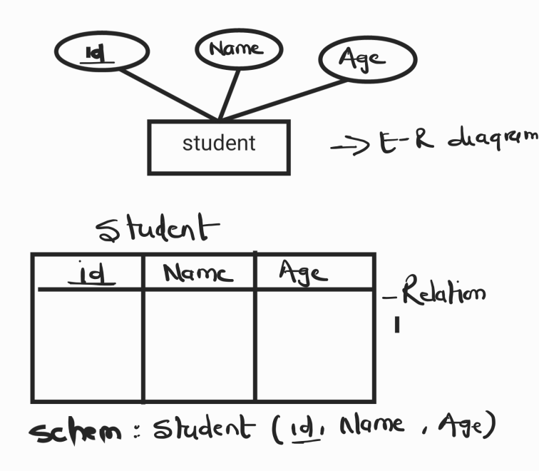
Mapping Entities to Tables
Each entity in the ER diagram is converted into a table. The attributes of the entity become the columns of the table. The primary key of the entity becomes the primary key of the table.
Example:
Entity: Student
- Attributes: StudentID (PK), Name, Age, Major
Table: Student
|
StudentID |
Name |
Age |
Major |
|
PK |
-
Mapping Entity Set With Only Simple Attributes to Tables
-
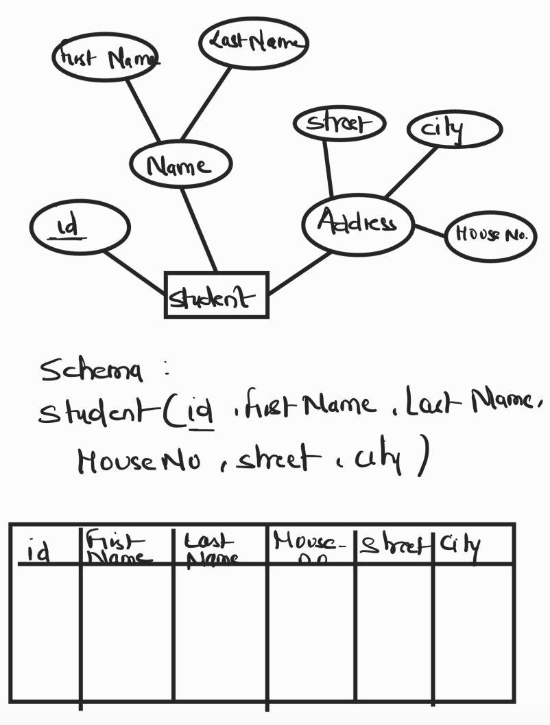
Mapping Entity Set With Composite Attributes into Table
c. Entity Set With Multi Valued Attributes
Example:
Entity: Employee
- Attributes: EmployeeID (PK), Name (composite of FirstName, LastName), DOB
Table: Employee
|
EmployeeID |
FirstName |
LastName |
DOB |
|
PK |
-
Mapping Entity Set With Multivalued Attributes into Table
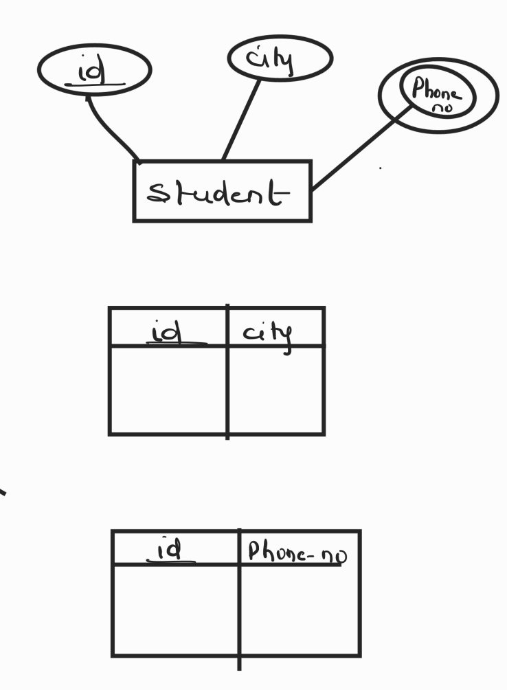
Multivalued attributes require a separate table. This table includes a foreign key referencing the primary key of the original entity and a column for each value of the multivalued attribute.
Example:
Entity: Student
- Attributes: StudentID (PK), Name, PhoneNumbers (multivalued)
Tables:
|
StudentID |
Name |
|
PK |
Multivalued Attribute Table: StudentPhoneNumbers
|
StudentID (FK) |
PhoneNumber |
|
FK |
-
Mapping Weak Entity into Table
Weak entities are entities that do not have a primary key of their own and depend on a "strong" entity. The table for a weak entity includes a foreign key referencing the primary key of the strong entity and its own attributes.
Example:
Entities: Order (strong), OrderItem (weak)
- Relationship: Order contains multiple OrderItems, but OrderItem cannot exist without Order.
Tables:
|
OrderID |
OrderDate |
|
PK |
|
OrderItemID |
OrderID (FK) |
ProductName |
Quantity |
|
PK |
FK |
-
Mapping Relationships to Tables
Relationships between entities are represented in tables. Depending on the type of relationship, this mapping can vary:
a. One-to-One (1:1) Relationship
A one-to-one relationship can be implemented by adding a foreign key to one of the tables. This foreign key references the primary key of the other table.
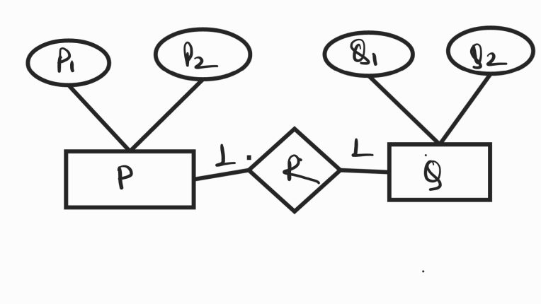
Here, two tables will be required. Either combine ‘R’ with ‘P’ or ‘Q’
- PR ( p1 , p2 , q1 )
- Q ( q1 , q2 )
OR
- P ( p1 , p2 )
- BR ( p1 , q1 , q2 )
Example:
Entities: Student, Dorm
- Relationship: Each student is assigned to one dorm, and each dorm has one student.
Tables:
|
StudentID |
Name |
Age |
Major |
DormID (FK) |
|
PK |
FK |
|
DormID |
DormName |
|
PK |
b. One-to-Many (1:N or M:1) Relationship
One to Many:
A one-to-many relationship is implemented by adding a foreign key to the table representing the "many" side of the relationship, referencing the primary key of the "one" side.
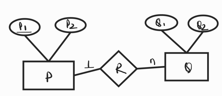
Here, two tables will be required-
- P ( p1 , p2 )
- QR ( p1 , q1 , q2 )
NOTE- The relationship table may or maynot be required . If required a combined table will be drawn for the entity set Q and relationship set R.
Many to One :
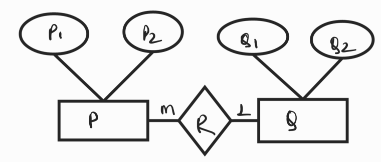
Here, two tables will be required-
-
PR ( p1 , p2 , q1 )
-
Q ( q1 , q2 )
NOTE- The relationship table may or maynot be required . If required a combined table will be drawn for the entity set P and relationship set R.
Example:
Entities: Department, Professor
- Relationship: One department has many professors, but each professor belongs to one department.
Tables:
|
DepartmentID |
DeptName |
|
PK |
|
ProfessorID |
Name |
Age |
DepartmentID (FK) |
|
PK |
FK |
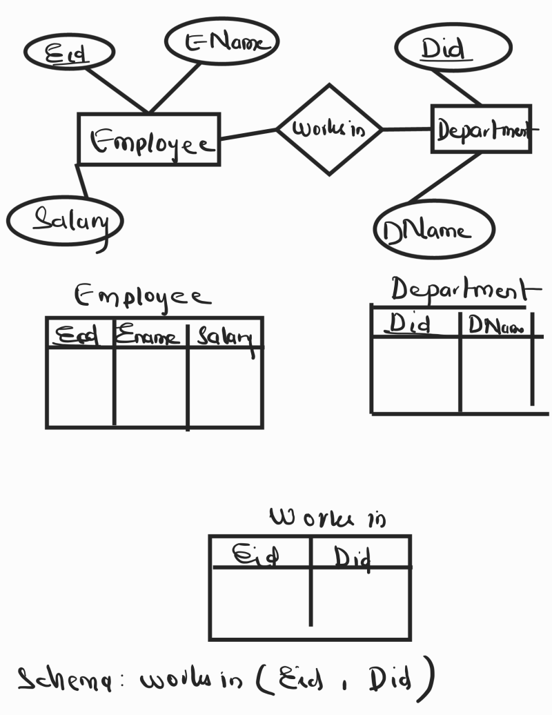
c. Many-to-Many (M:N) Relationship
A many-to-many relationship is represented by creating a new table (junction table) to capture the relationship. This table includes foreign keys referencing the primary keys of the related entities.
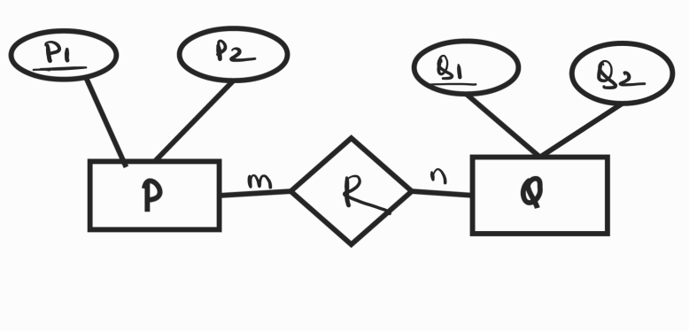
Three tables will be required
- P ( p1 , p2 )
- R ( p1 , q1 )
- Q ( q1 , q2 )
Example:
Entities: Student, Course
- Relationship: Students enroll in many courses, and each course has many students.
Tables:
|
StudentID |
Name |
Age |
Major |
|
PK |
|
CourseID |
CourseName |
|
PK |
Junction Table: Enrollment
|
StudentID (FK) |
CourseID (FK) |
EnrollmentDate |
|
FK |
FK |
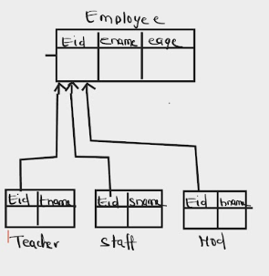
3.Mapping of Specialization or Generalization
There are several options for mapping a number of subclasses that together form a specialization (or alternatively, that are generalized into a superclass), such as the {SECRETARY, TECHNICIAN, ENGINEER} subclasses of EMPLOYEE.
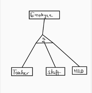
maps to
Some Key Terms to Remember
- Entities become Tables.
- Attributes become Columns.
- Primary Keys remain as Primary Keys.
- Foreign Keys are added to represent relationships.
- One-to-One relationships are implemented by a foreign key in one of the tables.
- One-to-Many relationships are implemented by a foreign key in the "many" side table.
- Many-to-Many relationships are implemented by creating a new table with foreign keys referencing both related entities.
- Multivalued Attributes require a separate table.
- Weak Entities are represented with a table that includes a foreign key to the strong entity.
PRACTICE QUESTION:
E-R DIAGRAM TO REALATION TABLE
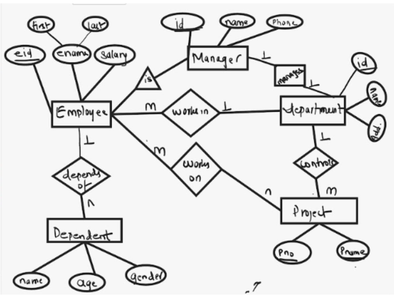
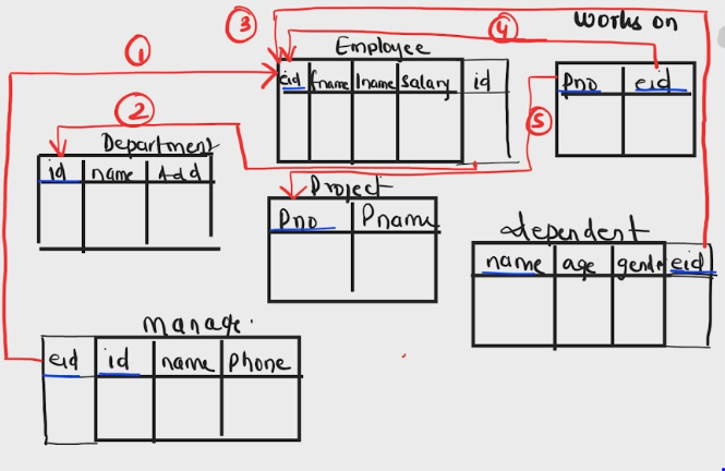
1. Manager and Employee has (is-a ) relation , so primary key of employee(eid) table should be foreign key of manager table.
2. M employee works in 1 department , hence it has m:1 relationship, so primary key of depatrmet(id) table is the foreign key of employee table.
3. Dependent is a weak entity , hence primary key of employee(eid) table is the foreign key of Dependent table.
4 and 5.Employee works on a project has m:n relationship , hence three tables are formed and both primary key of employee(eid) and project(pno) are foreign key in works on table .