- Definition, Uses And Benefits
- Overview Of Network Topologies
- Overview Of Network Types
- Protocols And Standards
- Osi Reference Model
- Tcp/Ip Model
- Comparison Of Osi And Tcp/Ip
- Connectionless And Connection Oriented Network Services
- Internet, Isp, Backbone Overview
- Client Server And Peer To Peer Network
- Assignemnt -Chapter 1
- Chapter 1 Slides-Bca
- Chapter 1 Slides-Bsccsit
- Definition And Function
- Overview Of Llc And Mac
- Framing
- Flow Control
- Channel Allocation Techniques
- Ethernet Standards
- Dll Protocol
- Hamming Code-(Error Detection And Correction)
- Asynchronous Transfer Mode(Atm)
- Ieee 802.11
- Error Detection And Correction
- Parity Check - Error Detection
- Checksum -Error Detection
- Crc- Cyclic Redundancy Code
- Data Link Layer - Slides
- Introduction And Function
- Ipv4 Addressing And Subnetting
- Classful Address And Classless Addressing
- Ipv6 Addressing And Features
- Ipv4 And Ipv6 Header Format
- Comparision Of Ipv4 And Ipv6
- Example Address: Unicast, Multicast And Broadcast
- Example Address: Unicast, Multicast And Broadcast
- Routing And Routing Table
- Types Of Routing (Static Vs Dynamic, Unicast Vs Multicast,Link State Vs Distance Vector, Interior Vs Exterior)
- Routing Algorithm
- Routing Protocols
- Ipv4 To Ipv6 Transition Mechanism
- Icmp And Icmpv6
- Nat
- Network Traffic Analysis
- Firewall
- Access Control List
- Path Computation Algorithm
- Subnetting Numerical
- Lab 5:Basic Router Configuration
- Static Routing
- Dynamic Routing
- Creation Of Vlan And Trunking
- Creating A Lan And Connectivity Test In Lan
- Lab 3: Basic Network Command
- Implement Firewall Using Packet Tracer
- Basic Firewall Implementation
- Dns And Web Server Configuration
- Ftp
- Acl(Access Control List)
- Ethernet Cabling- Straight And Crossover
- Lab 1: Prepare A Hardware And Software Specification For Basic Computer System
- Lab 3: Determine Appropriate Placement Of Networking Device On A Network
a) HDLC
A high-level data link control (HDLC) is a protocol that is a bit-oriented synchronous data link layer. HDLC ensures the error-free transmission of data to the proper destinations and controls the data transmission speed.
HDLCs can provide both connection-oriented and connectionless services.
A high-level data link control defines rules for transmitting data between network points. Data in an HDLC is organized into units called frames and is sent across networks to specified destinations. HDLC also manages the pace at which data is transmitted. HDLC is commonly used in the open systems interconnection (OSI) model's layer.
HDLC frames are transmitted over synchronous links or asynchronous links, which do not mark the start and end of frames. This is done using a frame delimiter or flag, which contains unique sequence of bits that are not visible inside a frame.
There are three types of HDLC frames:
- Information frames/User data (I-frames)
- Supervisory frames/Control data (S-frames)
- Unnumbered frames (U-frames)
The common fields within an HDLC frame are:
- Flag
- Address
- Control information
- Frame check sequence
The HDLC protocol is used by a variety of standards implemented in the protocol stacks of X.25, V.42 and ISDN and many other protocol stacks.
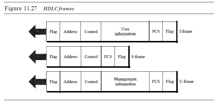
o Flag field. The flag field of an HDLC frame is an 8-bit sequence with the bit pattern 01111110 that identifies both the beginning and the end of a frame and serves as a synchronization pattern for the receiver.
o Address field. The second field of an HDLC frame contains the address of the secondary station. If a primary station created the frame, it contains a to address. If a secondary creates the frame, it contains a from address. An address field can be 1 byte or several bytes long, depending on the needs of the network. One byte can identify up to 128 stations (l bit is used for another purpose). Larger networks require multiple-byte address fields. If the address field is only 1 byte, the last bit is always a 1. If the address is more than 1 byte, all bytes but the last one will end with 0; only the last will end with 1. Ending each intermediate byte with 0 indicates
to the receiver that there are more address bytes to come.
o Control field. The control field is a 1- or 2-byte segment of the frame used for flow and error control. The interpretation of bits in this field depends on the frame type. We discuss this field later and describe its format for each frame type.
o Information field. The information field contains the user's data from the network layer or management information. Its length can vary from one network to another.
o FCS field. The frame check sequence (FCS) is the HDLC error detection field. It can contain either a 2- or 4-byte ITU-T CRC.
b) PPP
In computer networking, Point-to-Point Protocol (PPP) is a data link (layer 2) protocol used to establish a direct connection between two nodes. It connects two routers directly without any host or any other networking device in between. It can provide connection authentication, transmission encryption (using ECP, RFC 1968), and compression.
PPP is used over many types of physical networks including serial cable, phone line, trunk line, cellular telephone, specialized radio links, and fiber optic links such as SONET.
1. It defines link control protocol (LCP) for:-
(a) Establishing the link between two devices.
(b) Maintaining this established link.
(c) Configuring this link.
(d) Terminating this link after the transfer.
2. It defines how network layer data are encapsulated in data link frame.
3. PPP provides error detection.
4. Unlike SLIP that supports only IP, PPP supports multiple protocols.
5. PPP allows the IP address to be assigned at the connection time i.e. dynamically. Thus a temporary IP address can be assigned to each host.
6. PPP provides multiple network layer services supporting a variety of network layer protocol. For this PPP uses a protocol called NCP (Network Control Protocol).
8. It also defines how two devices can authenticate each other.
PPP Frame Format
The frame format of PPP resembles HDLC frame. Its various fields are:
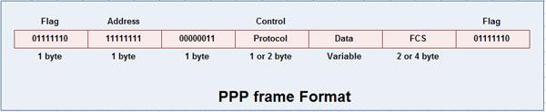
1. Flag field: Flag field marks the beginning and end of the PPP frame. Flag byte is 01111110. (1 byte).
2. Address field: This field is of 1 byte and is always 11111111. This address is the broadcast address i.e. all the stations accept this frame.
3. Control field: This field is also of 1 byte. This field uses the format of the U-frame (unnumbered) in HDLC. The value is always 00000011 to show that the frame does not contain any sequence numbers and there is no flow control or error control.
4. Protocol field: This field specifies the kind of packet in the data field i.e. what is being carried in data field.
5. Data field: Its length is variable. If the length is not negotiated using LCP during line set up, a default length of 1500 bytes is used. It carries user data or other information.
6. FCS field: The frame checks sequence. It is either of 2 bytes or 4 bytes. It contains the checksum.