Describing and Elaborating Use Cases
Use-Case Realizations
To quote, "A use-case realization describes how a particular use case is realized within the design model, in terms of collaborating objects" [RUP]. More precisely, a designer can describe the design of one or more scenarios of a use case; each of these is called a use-case realization. Use-case realization is a UP term or concept used to remind us of the connection between the requirements expressed as use cases, and the object design that satisfies the requirements.
UML interaction diagrams are a common language to illustrate use-case realizations.
To review, Figure 17.20 (near the end of this chapter) illustrates the relationship between some UP artifacts:
- The use case suggests the system events that are explicitly shown in system sequence diagrams.
- Details of the effect of the system events in terms of changes to domain objects may optionally be described in system operation contracts.
- The system events represent messages that initiate interaction diagrams, which illustrate how objects interact to fulfill the required tasks—the use case realization.
- The interaction diagrams involve message interaction between software objects whose names are sometimes inspired by the names of conceptual classes in the Domain Model, plus other classes of objects.
Interaction Diagrams and Use-Case Realizations
In the current iteration we are considering various scenarios and system events such as:
- Process Scale: makeNewSale, enterItem, endSale, makePayment
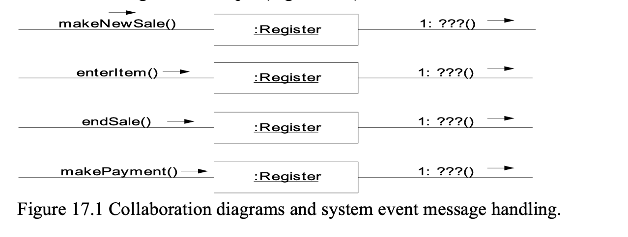
If collaboration diagrams are used to illustrate the use-case realizations, a different collaboration diagram will be required to show the handling of each system event message:
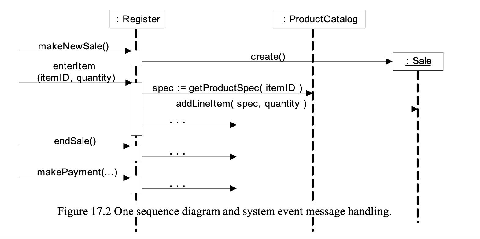
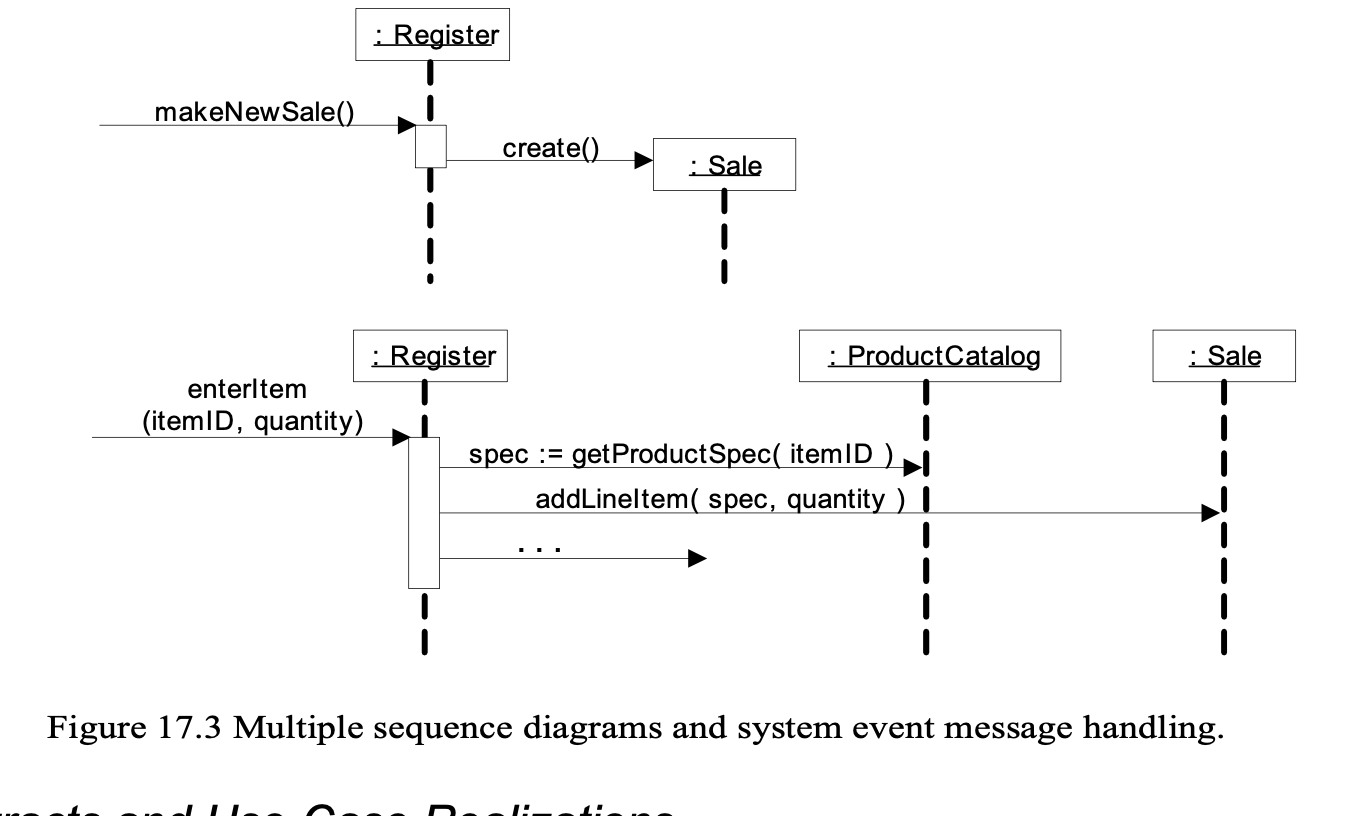
On the other hand, if sequence diagrams are used, it may be possible to fit all system event messages on the same diagram, as in Figure 17.2.
However, it is often the case that the sequence diagram is too complex or long. It is legal, as with interaction diagrams, to use a sequence diagram for each system event message, as in Figure 17.3.
Use-Case Realizations for the NextGen Iteration
Object Design: makeNewSale
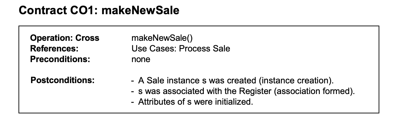
The makeNewSale system operation occurs when a cashier requests to start a new sale, after a customer has arrived with things to buy. The use case may have been sufficient to decide what was necessary, but for this case study we wrote contracts for all the system events, for explanation and completeness.
Creating a New Sale
A software Sale object must be created, and the GRASP Creator pattern sug- gests assigning the responsibility for creation to a class that aggregates, contains, or records the object to be created.
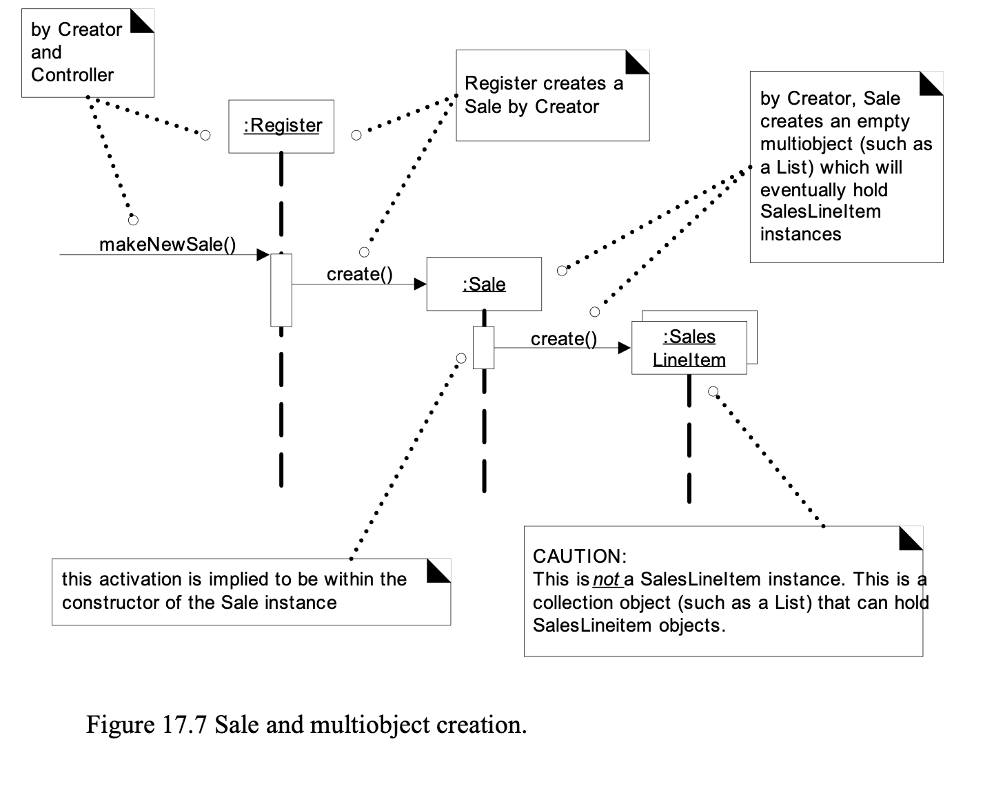
Analyzing the Domain Model reveals that a Register may be thought of as recording a Sale; indeed, the word "register" in business has for many years meant the thing that recorded (or registered) account transactions, such as sales.
Thus, Register is a reasonable candidate for creating a Sale. And by having the Register create the Sale, the Register can easily be associated with it over time, so that during future operations within the session, the Register will have a reference to the current Sale instance.
In addition to the above, when the Sale is created, it must create an empty col- lection (container, such as a Java List) to record all the future SalesLineItem instances that will be added. This collection will be contained within and maintained by the Sale instance, which implies by Creator that the Sale is a good candidate for creating it.
Therefore, the Register creates the Sale, and the Sale creates an empty collec- tion, represented by a multi object in the interaction diagram.
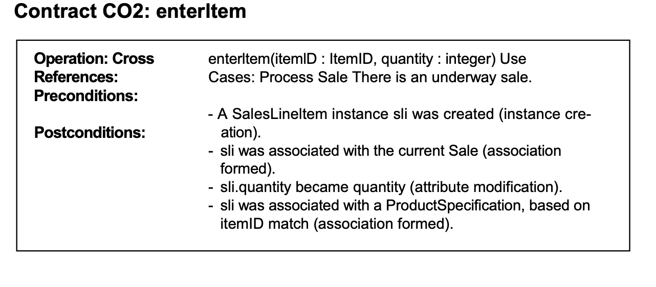
Object Design: enterltem
The enterItem system operation occurs when a cashier enters the itemID and (optionally) the quantity of something to be purchased. Here is the complete contract: