Class Diagram
With the completion of interaction diagrams for use-case realizations for the current iteration of the NextGen POS application, it is possible to identify the specification for the software classes (and interfaces) that participate in the software solution, and annotate them with design details, such as methods.
When to Create Design Class Diagrams
Although this presentation of DCDs follows the creation of interaction diagrams, in practice they are usually created in parallel. Many classes, method names and relationships may be sketched out very early in design by applying responsibility assignment patterns, prior to the drawing of interaction diagrams. It is possible and desirable to do a little interaction diagramming, then update the DCDs, then extend the interaction diagrams some more, and so on.
Example DCD
DCD and UP Terminology
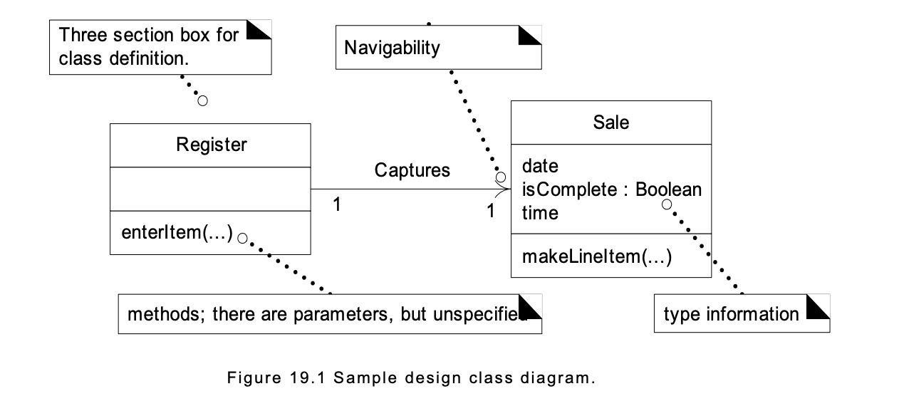
A design class diagram (DCD) illustrates the specifications for software classes and interfaces (for example, Java interfaces) in an application. Typical information includes: • classes, associations and attributes • interfaces, with their operations and constants • methods • attribute type information • navigability • dependencies
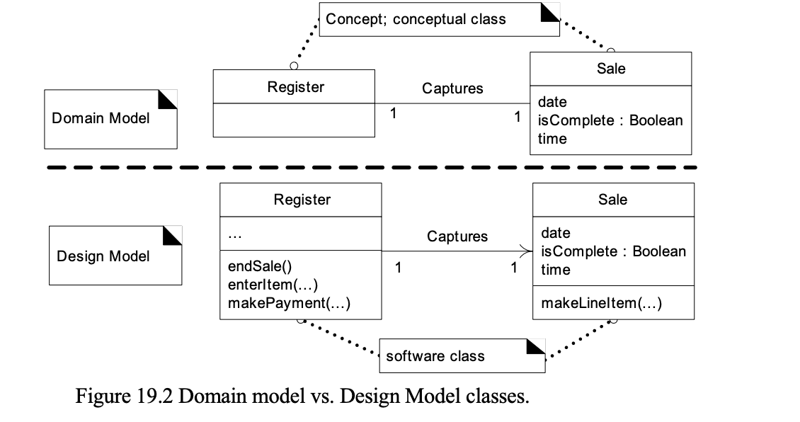
In contrast to conceptual classes in the Domain Model, design classes in the DCDs show definitions for software classes rather than real-world concepts.
The UP does not specifically define an artifact called a "design class diagram." The UP defines the Design Model, which contains several diagram types, including interaction, package, and class diagrams. The class diagrams in the UP Design Model contain "design classes" in UP terms. Hence, it is common to speak of "design class diagrams," that is shorter than, and implies, "class diagrams in the Design Model."
Domain Model vs. Design Model Classes
To reiterate, in the UP Domain Model, a Sale does not represent a software definition; rather, it is an abstraction of a real-world concept about which we are interested in making a statement. By contrast, DCDs express—for the software application—the definition of classes as software components. In these diagrams, a Sale represents a software class .
Creating a NextGen POS DCD
Identify Software Classes and Illustrate Them
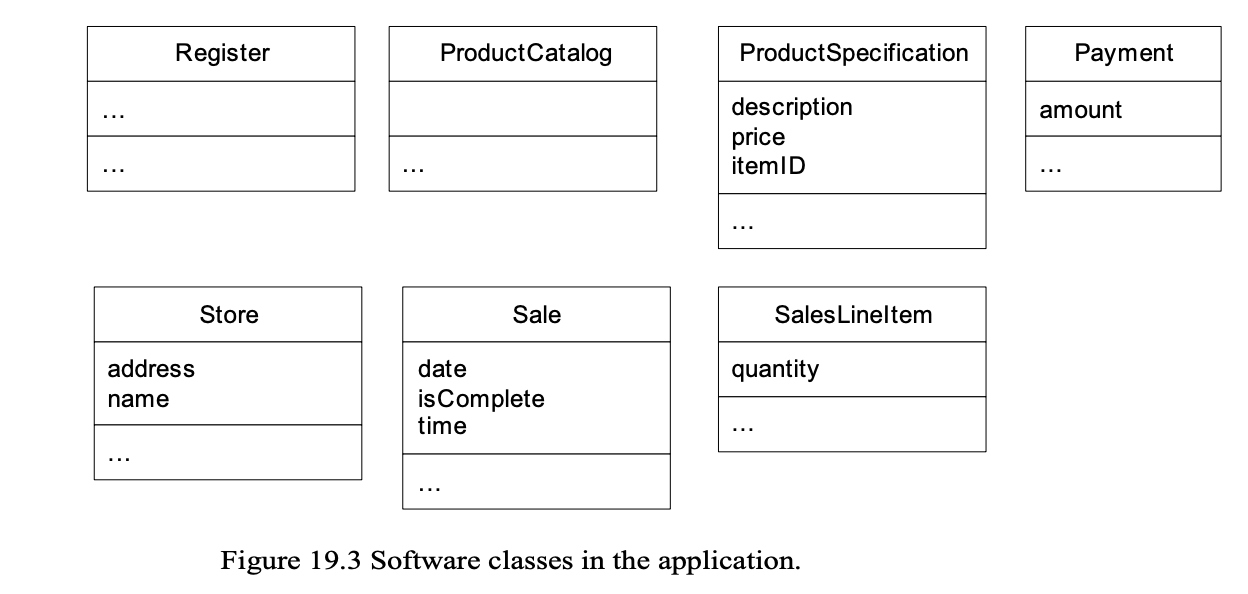
The first step in the creation of DCDs as part of the solution model is to identify those classes that participate in the software solution. These can be found by scanning all the interaction diagrams and listing the classes mentioned.
For the POS application, these are:
Register
ProductCatalog
Store
Payment
Sale
ProductSpecification
SalesLineItem
The next step is to draw a class diagram for these classes and include the attributes previously identified in the Domain Model that are also used in the design Note that some of the concepts in the Domain Model, such as Cashier, are not present in the design. There is no need—for the current iteration—to represent them in software. However, in later iterations, as new requirements and use cases are tackled, they may enter into the design. For example, when security and log-in requirements are implemented, it is likely that a software class named Cashier will be relevant.
Add Method Names
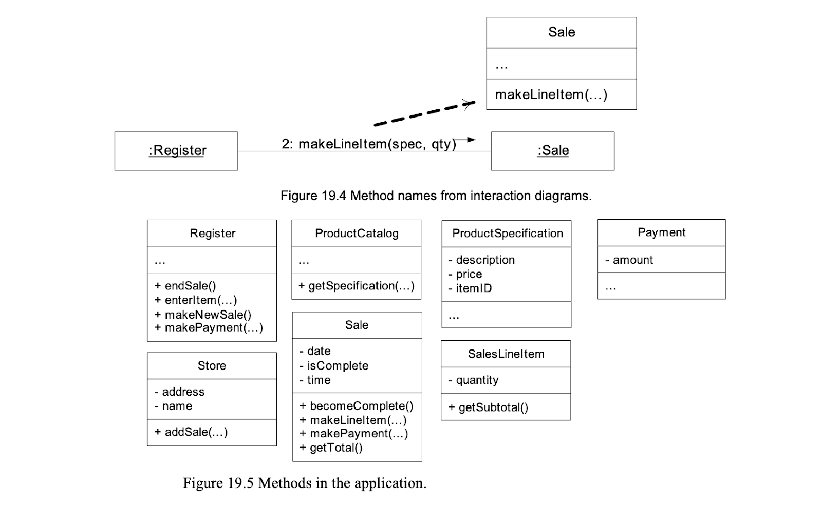
The methods of each class can be identified by analyzing the interaction diagrams. For example, if the message makeLineItem is sent to an instance of class Sale, then class Sale must define a makeLineItem method (see Figure 19.4). In general, the set of all messages sent to a class X across all interaction diagrams indicates the majority of methods that class X must define. Inspection of all the interaction diagrams for the POS application yields the allocation of methods shown in Figure 19.5.
Method Name Issues
The following special issues must be considered with respect to method names: • interpretation of the create message • depiction of accessing methods • interpretation of messages to multiobjects • language-dependent syntax
Method Names—create
The create message is a possible UML language independent form to indicate instantiation and initialization. When translating the design to an object-oriented programming language, it must be expressed in terms of its idioms for instantiation and initialization. There is no actual create method in C++, Java,or Smalltalk. For example, in C++, it implies automatic allocation, or free store allocation with the new operator, followed by a constructor call. In Java, it implies the invocation of the new operator, followed by a constructor call. Because of its multiple interpretations, and also because initialization is a very common activity, it is common to omit creation-related methods and constructors from a DCD.
Method Names—Accessing Methods
Accessing methods retrieve (accessor method) or set (mutator method) attributes. In some languages (such as Java) it is a common idiom to have an accessor and mutator for each attribute, and to declare all attributes private (to enforce data encapsulation). These methods are usually excluded from depiction in the class diagram because of the high noise-to-value ratio they generate; for n attributes, there are 2n uninteresting methods. For example, the Product-Specification's getPrice (or price) method is not shown, although present, because getPrice is a simple accessor method.
Method Names—Multiobjects
A message to a multiobject is interpreted as a message to the container/collection object itself. For example, the following find message to the multiobject is meant be interpreted as a message to the container/collection object, such as to a Java Map, a C++ map or a Smalltalk Dictionary.
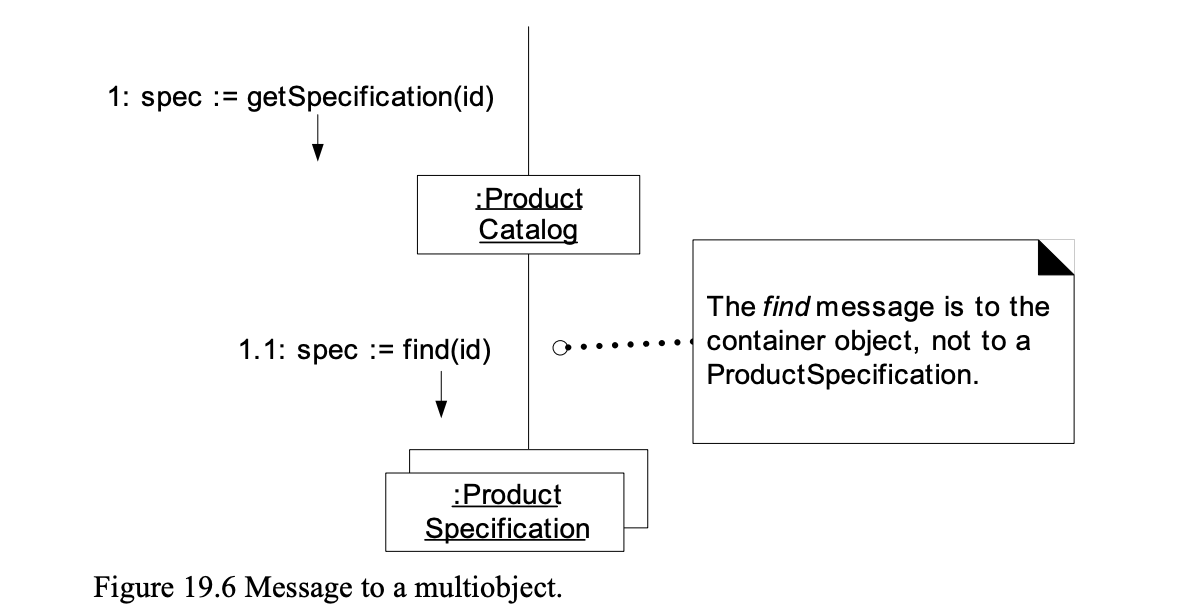
Therefore, the find method is not part of the Productspecification class; rather, it is part of the multiobject's interface. Consequently, it is incorrect to add find as a method to the Productspecification class.
These container/collection interfaces or classes (such as the interface java.util.Map) are usually predefined library elements, and it is not useful to show these classes explicitly in the DCD, since they add noise, but little new information.
Method Names—Language-Dependent Syntax
Some languages, such as Smalltalk, have a syntax that is very different from the basic UML format of methodName(parameterList). It is recommended that the basic UML format be used, even if the planned implementation language uses a different syntax. The translation should ideally take place during code generation time, instead of during the creation of the class diagrams. However, the UML does allow other syntax for method specification. Adding More Type Information The types of the attributes, method parameters, and method return values may all optionally be shown. The question as to whether to show this information or not should be considered in the following context:
The DCD should be created by considering the audience. • If it is being created in a CASE tool with automatic code generation, full and exhaustive details are necessary. • If it is being created for software developers to read, exhaustive low-level detail may adversely affect the noise-to-value ratio.
For example, is it necessary to show all the parameters and their type information? It depends on how obvious the information is to the intended audience.
Adding Associations and Navigability
Each end of an association is called a role, and in the DCDs the role may be decorated with a navigability arrow. Navigability is a property of the role that indicates that it is possible to navigate uni-directionally across the association from objects of the source to target class. Navigability implies visibility—usually attribute visibility.
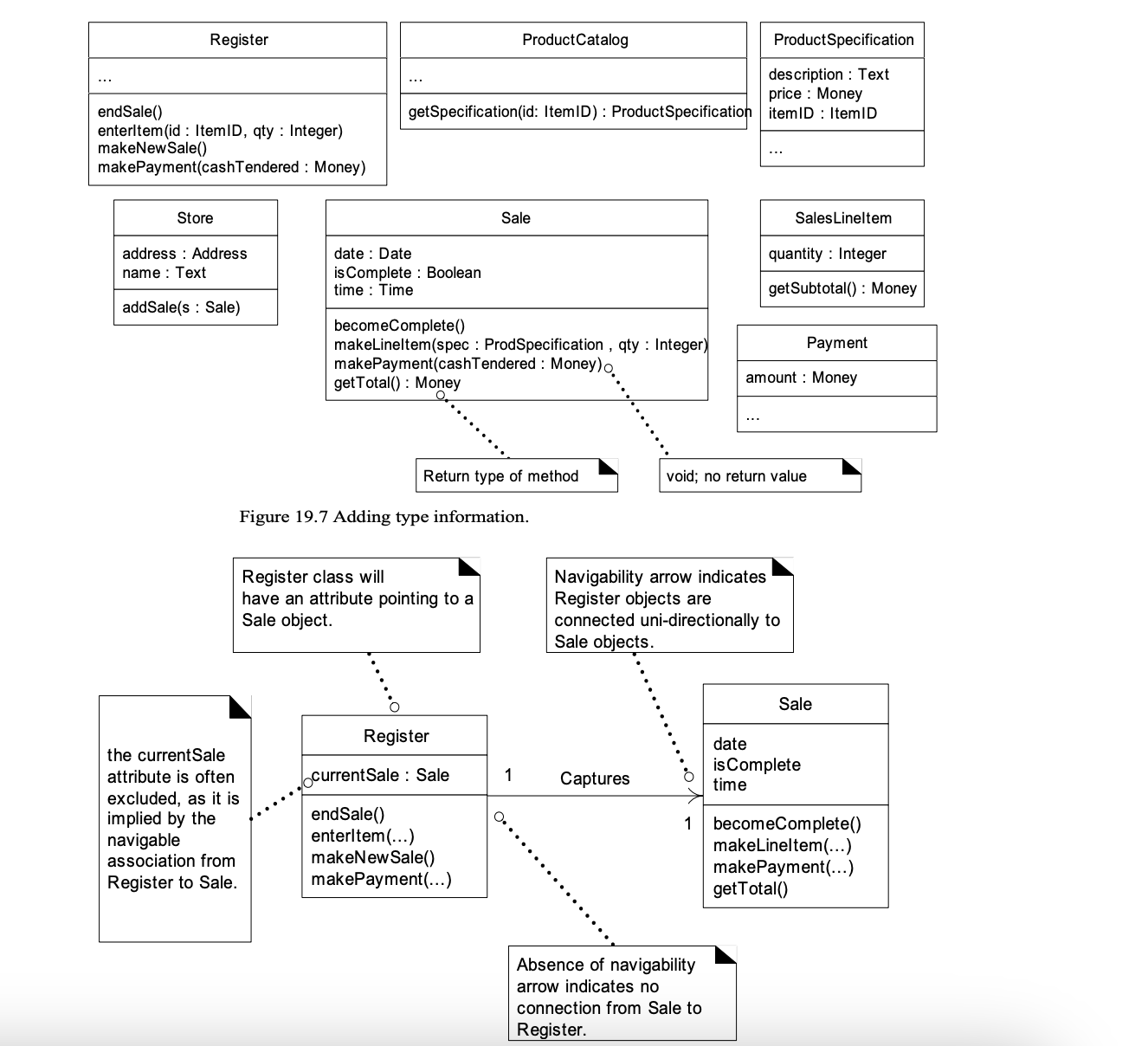
The usual interpretation of an association with a navigability arrow is attribute visibility from the source to target class. During implementation in an object-oriented programming language it is usually translated as the source class having an attribute that refers to an instance of the target class. For instance, the Register class will define an attribute that references a Sale instance
Most, if not all, associations in DCDs should be adorned with the necessary navigability arrows.
In a DCD, associations are chosen by a spartan software-oriented, need-to-know criterion—what associations are required to satisfy the visibility and ongoing memory needs indicated by the interaction diagrams? This is in contrast with associations in the Domain Model, which may be justified by the intention to enhance comprehension of the problem domain. Once again, we see a distinction between the goals of the Design Model and the Domain Model: one is analytical, the other a description of software components. The required visibility and associations between classes are indicated by the interaction diagrams. Here are common situations suggesting a need to define an association with a navigability adornment from A to B:
• A sends a message to B.
• A creates an instance B.
• A needs to maintain a connection to B.
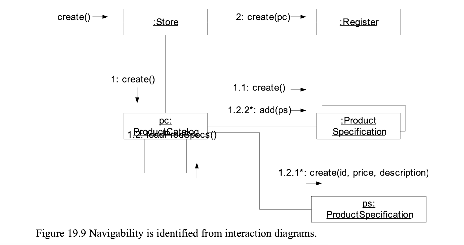
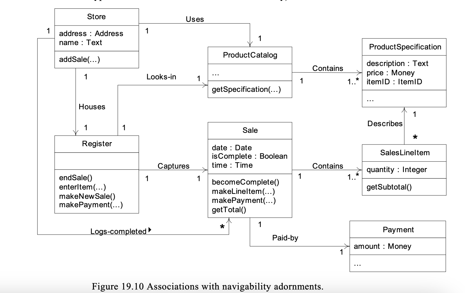
For example, from the interaction diagram in Figure 19.9 starting with the create message to a Store, and from the larger context of the other interaction diagrams, it is discernible that the Store should probably have an ongoing connection to the Register and ProductCatalog instances that it created. It is also reasonable that the ProductCatalog needs an ongoing connection to the collection of Product Specifications it created. In fact, the creator of another object very typically requires an ongoing connection to it. The implied connections will therefore be present as associations in the class diagram. Based on the above criterion for associations and navigability, analysis of all the interaction diagrams generated for the NextGen POS application will yield a class diagram (seen in Figure 19.10) with the following associations (exhaustive type information is hidden for the sake of clarity).
Adding Dependency Relationships
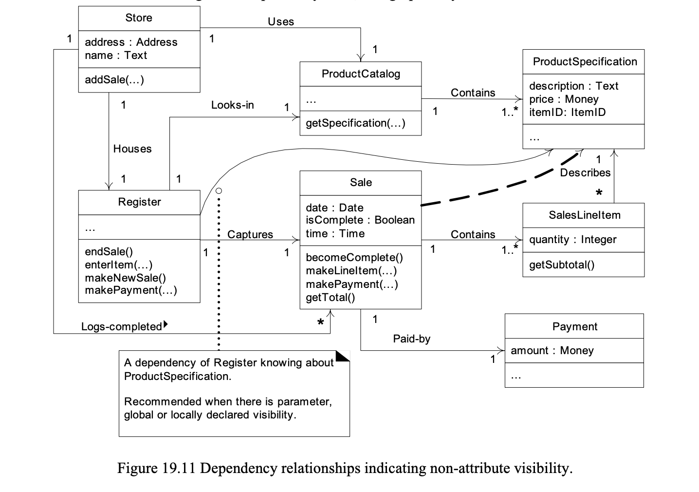
The UML includes a general dependency relationship, which indicates that one element (of any kind, including classes, use cases, and so on) has knowledge of another element. It is illustrated with a dashed arrow line. In class diagrams the dependency relationship is useful to depict non-attribute visibility between classes; in other words, parameter, global, or locally declared visibility. By contrast, plain attribute visibility is shown with a regular association line and a navigability arrow. For example, the Register software object receives a return object of type ProductSpecification from the specification message it sent to a ProductCatalog. Thus Register has a short-term locally declared visibility to ProductSpecifications. And Sale receives a ProductSpecification as a parameter in the makeLineItem message; it has parameter visibility to one. These non-attribute visibilities may be illustrated with the dashed arrow line indicating a dependency relationship (see Figure 19.11). There is no significance in the curving of the dependency lines; it is graphically convenient.